
2.2. Configuration Vector
The configuration vector selects which joint solution the voraus Robot Control uses when it converts a Cartesian pose into joint positions (inverse kinematics).
2.2.1. Definition and Physical Meaning
A Cartesian pose does not describe the state of a robot completely: the inverse kinematics is ambiguous. Several joint configurations, i.e., several postures of the arm (for example with the elbow pointing upwards or downwards), lead to the same Cartesian pose. These configurations are separated from each other by singularities of the kinematics (for example the shoulder, elbow and wrist singularity of a six-axis robot arm): within one configuration the joint positions change continuously with the Cartesian pose, while switching to another configuration always requires passing through the corresponding singularity.
The configuration vector resolves this ambiguity. It is an array in which every element is a flag with the value
+1 or -1 that selects one of the two configurations separated by one singularity of the kinematics.
A kinematics with \(n\) flags therefore has up to \(2^{n}\) different joint solutions for the same Cartesian
pose. A solution is only usable if all resulting joint positions lie within the configured axis position limits (see
Limitations).
Note
The configuration vector is only relevant for poses that are specified in a Cartesian coordinate system. A target
that is specified in the Joint CS (JOINT_CS) already defines the joint positions unambiguously, so no
inverse kinematics and therefore no configuration vector is needed.
2.2.2. Number of Elements
The number of flags is fixed for a given robot; it is determined by the KinematicsType entry of the robot
configuration file (see Robot Config File). Table 4 lists the number of
flags of all supported kinematics types.
Note
The OPC UA interface transports the configuration vector as an array of up to six elements, independently of the
connected robot: elements beyond the number of flags required by the robot’s kinematics are ignored on input and
set to 1 on output. An input array with fewer elements than required is rejected as invalid.
2.2.3. Specifying a Configuration
Cartesian Motion Targets
The PTP command accepts an optional configuration vector via its ConfigVector parameter, see the
ConfigVector entry in Table 79. It is evaluated when the target is specified in a
Cartesian coordinate system:
If the configuration vector contains only zeros or is empty, no configuration is requested. The motion planner then determines the target configuration on its own, primarily by keeping the current configuration of the robot, see Target Coordinates.
If at least one element is non-zero, the configuration vector is applied. All flags required by the robot’s kinematics must then be provided and each of them must be either
+1or-1, otherwise the command is rejected.
The LIN and CIRC commands do not accept a configuration vector: a Cartesian path is always executed in the configuration that the robot has at the start of the command, because changing it would require moving through a singularity. A configuration is therefore always changed by a PTP motion.
Kinematic Transformations
The InverseKinematic function of the OPC UA interface takes a configuration vector as an input argument in
order to select the joint solution to be calculated. If an empty array is submitted, the currently commanded
configuration of the robot is used instead, see Inverse Kinematic.
The configuration of a given joint pose can also be read back, which is the recommended way to determine the flag values of a specific arm configuration:
The
ForwardKinematicfunction of the OPC UA interface returns, next to the Cartesian pose, the configuration vector of the submitted joint positions, see Forward Kinematic.The currently commanded configuration of the robot is published cyclically as
RobotCommandedConfigurationon the OPC UA interface.
Both functions are described in the section Kinematic Transformations.
2.2.4. Example: Six-Axis Robot Arm with Three Flags
A six-axis robot arm of the kinematics type CrossedWrist6R (e.g., a KUKA robot) has three flags, so the same
Cartesian pose of the Tool CS can be reached with up to eight different sets of joint positions.
Each flag switches between two configurations without changing the pose of the Tool CS. Which of the eight combinations
can actually be used depends on the axis position limits of the specific robot.
The first flag selects the configuration of the shoulder (axis 1), i.e., whether the arm points towards the wrist or reaches backwards over its own base, see Fig. 6.
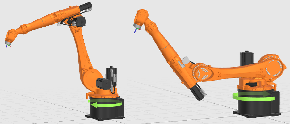
Fig. 6 Shoulder configuration: the arm points towards the wrist (left) or reaches backwards over its own base (right)
The second flag selects the configuration of the elbow, i.e., whether the elbow points upwards or downwards, see Fig. 7.
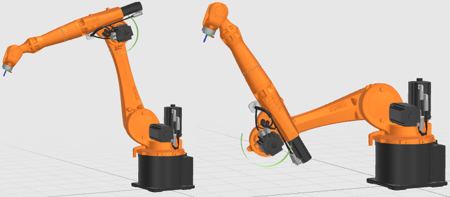
Fig. 7 Elbow configuration: elbow above (left) or below (right) the connecting line between shoulder and wrist
The third flag selects the configuration of the wrist. Both configurations lead to the same flange orientation, but axis 5 is rotated in the opposite direction and axes 4 and 6 differ by 180°, see Fig. 8.
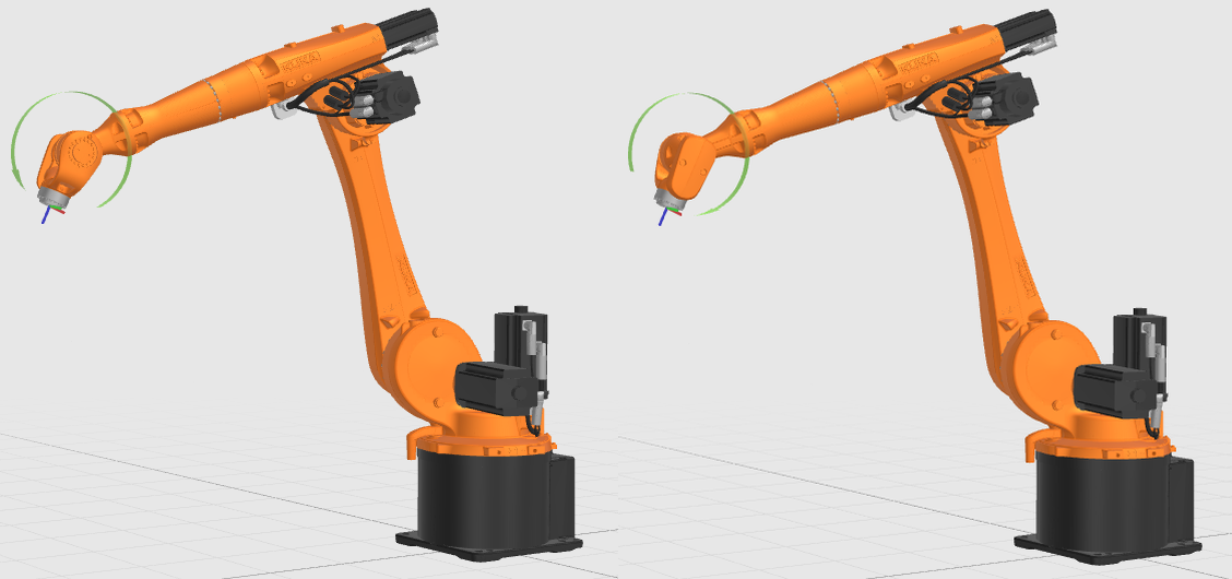
Fig. 8 Wrist configuration: the two wrist configurations that lead to the same flange orientation
2.2.5. Configuration Flags of the Supported Kinematics
The following sections list, for every kinematics type, which singularity and axis each of its flags resolves.
Note
Which of the two configurations a flag value selects depends on the axis convention of the robot (see Axes). The figures in this section and in Example: Six-Axis Robot Arm with Three Flags show the assignment for the respective kinematics; for a specific robot, the values of a known pose can be read back as described in Specifying a Configuration.
Six-Axis Robot Arms with Spherical Wrist
Kinematics type CrossedShifted6R_3, see Table 5.
Examples of configuration for a robot with spherical wrist are shown in Fig. 6,
Fig. 7, and Fig. 8. A robot with spherical
wrist and offset (kinematics type CrossedShifted6R_3 ) is shown in Fig. 9.
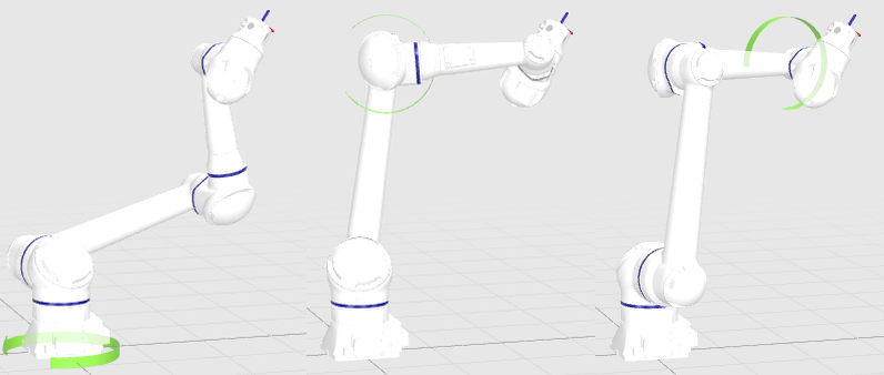
Fig. 9 Shoulder [-1, 1, 1], elbow [-1, -1, 1] and wrist [1, 1, -1] configurations of a six-axis
robot arm with a crossed and shifted wrist
Six-Axis Robot Arms with no Spherical Wrist
Kinematics types ParallelWrist6R-1 and ParallelWrist6R-2, see
Table 6 and Fig. 10.
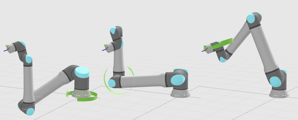
Fig. 10 Shoulder [-1, 1, 1], elbow [1, -1, 1] and wrist [1, 1, -1] configurations of a robot arm
with a parallel wrist
Four-Axis Palletizing Robots
Kinematics type DoubleParallelogram_4R. Palletizing robots can only reach a restricted set of tool
orientations: the tool always points downwards and only the rotation about the vertical axis is free. The wrist,
therefore, has no ambiguity and only two flags remain, see Table 7.
SCARA Robots
Kinematics type ScaraRRPR. A SCARA robot has a single flag, which selects the configuration of the elbow, see
Table 8 and Fig. 11.
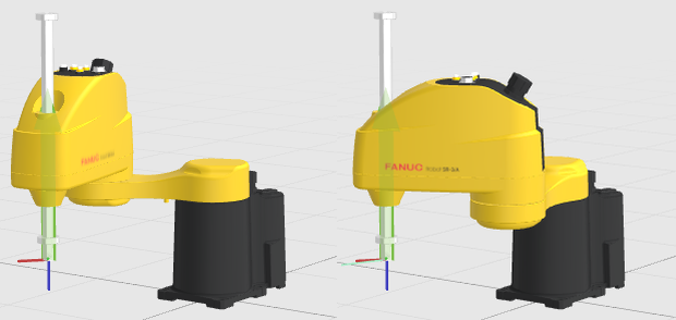
Fig. 11 Left-handed and right-handed elbow configuration of a SCARA robot
Gantry Robots
Kinematics type Gantry_XYZ_3P. The three prismatic axes of a gantry robot reach every pose within the
workspace with exactly one set of joint positions, and the tool orientation is fixed (see voraus Conventions).
The inverse kinematics is therefore unambiguous and the configuration vector is empty.