
5.1. voraus Conventions
This chapter describes the coordinate system conventions used within the voraus Robot Control. It provides an overview of all available coordinate systems and their relationships, explains how the coordinate system hierarchy is structured as a tree, and details how these conventions apply to different robot types such as serial six-axis robots, SCARA robots, and gantry robots. In addition, it covers the definition of user coordinate systems and summarizes the units used throughout the system.
5.1.1. Coordinate Systems Overview
The voraus Robot Control defines a set of standard coordinate systems (also called Cartesian reference frames). Each Cartesian coordinate system is related to the others through homogeneous transformation matrices. The following table lists all available coordinate systems along with their numeric API identifier, which is used to select a coordinate system programmatically through the OPC UA interface of the voraus Robot Control.
Coordinate System |
OPC UA ID |
Description |
|---|---|---|
Joint CS ( |
0 |
The joint coordinate system. This is not a Cartesian frame but represents the robot’s joint space. Each element corresponds to an individual joint angle (rotational) or joint displacement (prismatic). Joint angles are always specified in radians [rad] for rotational joints and in meters [m] for prismatic (translational) joints, see more information about units in the section Units Summary. |
Robot CS ( |
1 |
The primary Cartesian reference frame, usually fixed at the robot’s mounting point (i.e., the interface between the robot base and the surface it is mounted on), an example is shown in Fig. 24. All other Cartesian coordinate systems are ultimately referenced to this frame. Note This is the default coordinate system for specifying Cartesian poses. |
Tool CS ( |
2 |
A Cartesian coordinate system located at the robot’s tool center point (TCP). This frame moves dynamically with the end effector. If all tool transformation parameters are zero, the Tool CS coincides with the robot’s flange. An example of the placement of the Tool CS is shown in Fig. 24. See also the section Tool Transformation for more information. |
Camera CS ( |
3 |
A Cartesian coordinate system located at a camera mounted on the robot. Like the Tool CS, it moves dynamically with the end effector. It is configured through the system configuration. |
User CS 01–16 ( |
4–19 |
Up to 16 user-defined Cartesian coordinate systems. These can be freely configured at runtime to represent arbitrary frames of reference (e.g., a workpiece fixture, a pallet, or a conveyor). Unlike the Tool CS and Camera CS, User CS are fixed in space and do not move with the end effector. They are defined by specifying a pose relative to another coordinate system. |
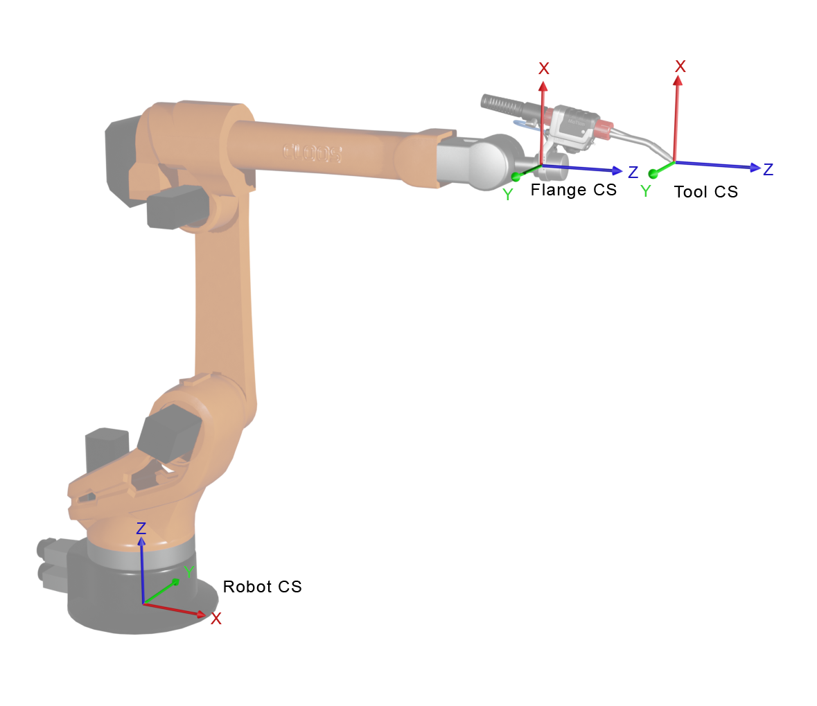
Fig. 24 Exemplary Cloos robot with Robot CS, Flange CS and Tool CS located at the TCP
In addition, the following arriving coordinate systems specify where the robot should arrive when executing a command to a specified target position. The numeric API identifier is used to select the arriving coordinate system in motion commands via the OPC UA interface of the voraus Robot Control.
Arriving CS |
OPC UA ID |
Description |
|---|---|---|
Tool CS ( |
0 |
Arrive at the TCP (default). |
Flange CS ( |
1 |
Arrive at the robot’s mechanical flange. The Flange CS corresponds to the last coordinate system derived from the DH parameters. It is managed internally by the voraus Robot Control and is used by other commands. An example is shown in Fig. 24. |
Camera CS ( |
2 |
Arrive at the camera’s reference point. |
5.1.2. Coordinate System Tree Structure
Coordinate systems in the voraus Robot Control are organized as a tree. Each coordinate system has exactly one parent (except the root) and may have multiple children. The tree structure ensures that moving a parent coordinate system automatically propagates the change to all of its children.
The default tree structure is:
Robot CS (it can differ from the usual manufacturer-specific origin)
└── Flange CS
│    ├── Tool CS
│    └── Camera CS
└── User CS 01 … User CS 16
Robot CS: Some robot manufacturers define their internal origin at a different location than the mounting point. For example, FANUC places its internal coordinate origin at axis 2. The voraus Robot Control handles the transformation between the manufacturer’s origin and the mounting point automatically.
Flange CS: Located at the robot’s mechanical flange (last axis output). The Tool CS and Camera CS are children of the Flange CS and move with it.
Tool CS: Defined by the currently active tool’s TCP transformation (see section Tool Transformation) and a configurable offset. Configured through Tool configuration.
Camera CS: Defined by the camera calibration offset relative to the flange.
User CS 01–16: Freely configurable by the user. They are children of the Robot CS, see section Defining User Coordinate Systems for more information.
5.1.3. Application to Different Robot Types
The coordinate system conventions apply consistently across all supported robot types. However, there are important differences in how the conventions map to the physical robot:
Serial Six-Axis Robots (e.g., KUKA)
For serial six-axis robot arms, the coordinate systems are defined as follows:
The Robot CS is located at the base of the robot (mounting point on the table or floor) as shown in Fig. 25.
The Flange CS is at the output of the sixth joint.
Joint angles correspond to the six rotational axes. The
RotationDirectionparameter specifies whether the positive direction of rotation aligns with or opposes the DH convention.Manufacturer-specific offsets: Robot manufacturers may define their zero pose differently from the DH-kinematic zero pose. These offsets are stored in the DH parameter’s
thetafield and applied automatically, see also the information aboutAxes.DHin the section Axes.
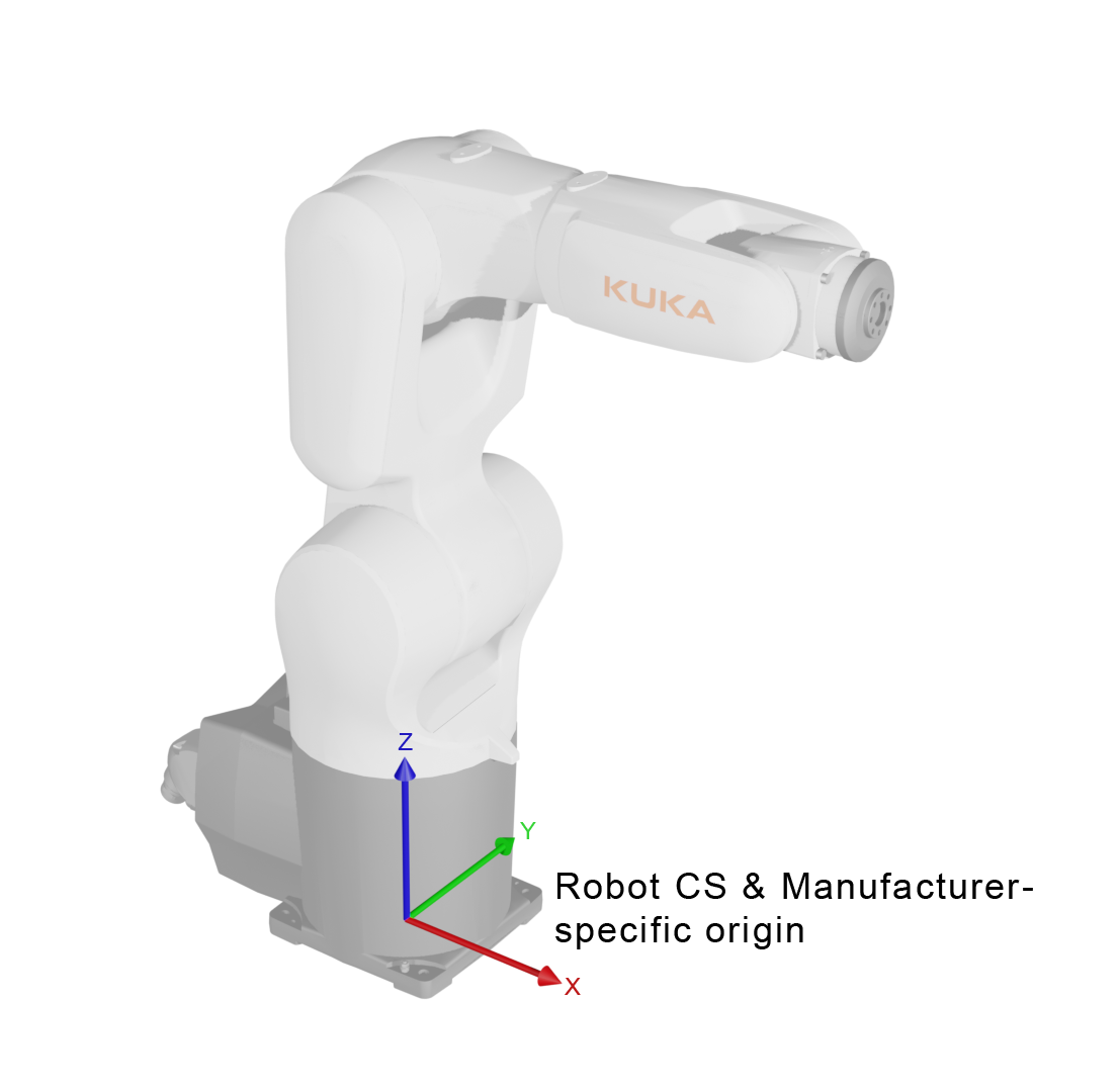
Fig. 25 Exemplary KUKA robot with Robot CS and manufacturer-specific origin at the base of the robot
Note
For FANUC robots, the Cartesian coordinates received from the robot controller use the convention
(x, y, z, W, P, R) in millimeters and degrees with an extrinsic xyz rotation order. The voraus Robot
Control automatically converts these into the voraus convention (x, y, z, A, B, C) in meters and radians
with the intrinsic X Y' Z'' (Cardan) rotation order.
SCARA Robots
For SCARA robots, the same coordinate system hierarchy applies:
The Robot CS is at the mounting point, as shown in Fig. 26.
SCARA robots typically have a combination of rotational and prismatic joints. The joint types (
ROTATIONAL/PRISMATIC) are configured per axis.Cartesian poses follow the same
[x, y, z, A, B, C]convention, although SCARA robots have limited orientational degrees of freedom. Therefore, coordinates A and B must be fixed. Only variation in coordinate C is allowed.
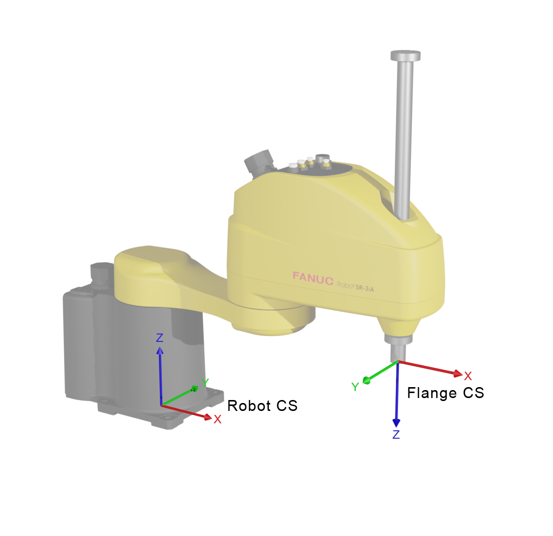
Fig. 26 Exemplary SCARA robot with Robot CS at the mounting point and Flange CS
Gantry Robots
Gantry (portal) robots use three prismatic (linear) joints for their axes:
The Robot CS is at one corner of the gantry system, see Fig. 27.
The kinematics are described using Denavit–Hartenberg (DH) parameters. The DH coordinate system (
CS0) may differ from the Robot CS. The transformationposeRobotCSToCS0defines the offset between them, see also the section Robot Config File for more information about robot configuration parameters.All three primary axes are prismatic (
x,y,ztranslations).The orientation of the tool is fixed (typically pointing downward). The robot verifies that the Cartesian orientation remains within the valid range for the gantry kinematics.
Joint coordinates are specified in meters [m] for the prismatic axes.
Cartesian poses follow the same [x, y, z, A, B, C] convention, although gantry robots have fixed orientation, i.e., A, B, and C angles have fix values.
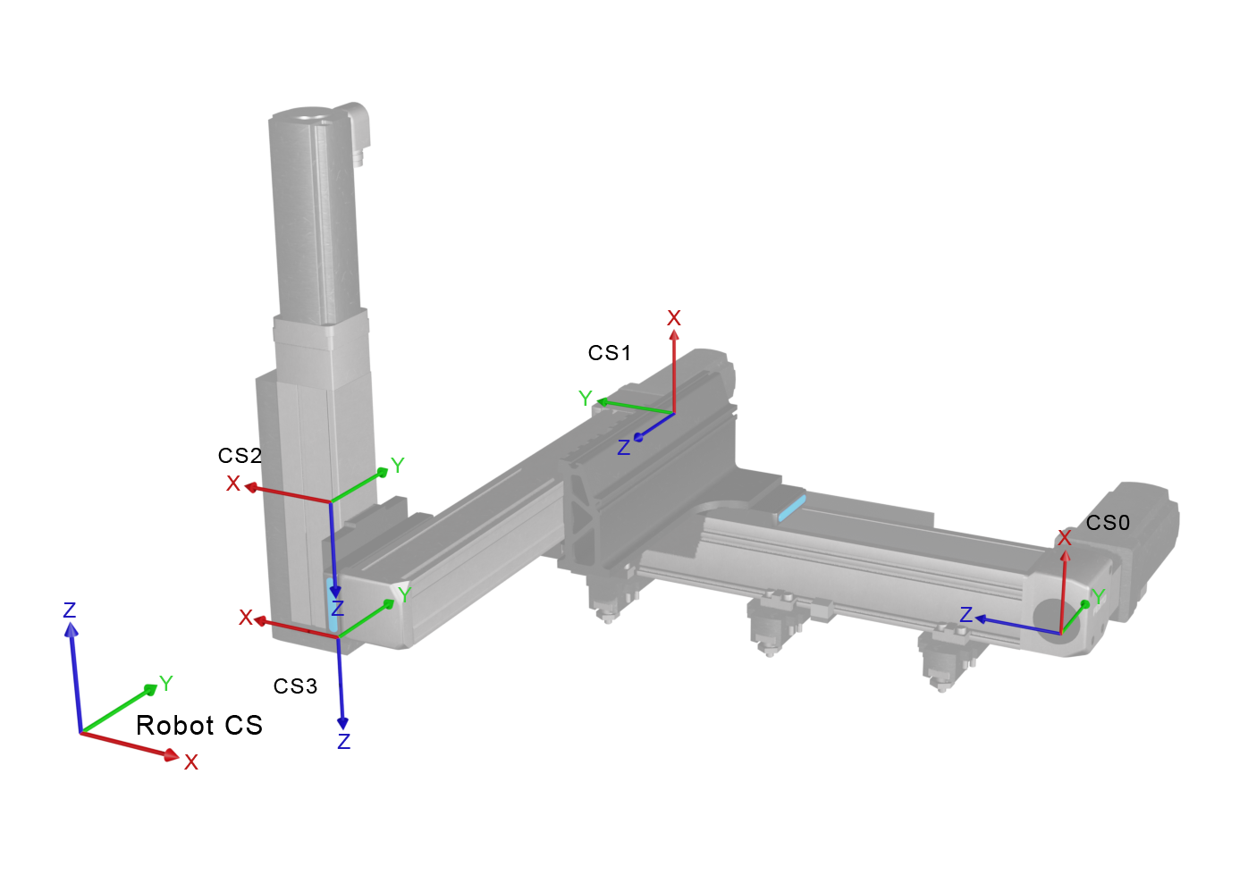
Fig. 27 Exemplary gantry robot: Robot CS is located at one corner of the gantry system, CS0 to CS3
are the DH coordinate systems.
5.1.4. Defining User Coordinate Systems
User coordinate systems can be defined at runtime to create custom reference frames. A user coordinate system is defined by providing:
A reference coordinate system — used to determine the pose of the new coordinate system
A pose — the
[x, y, z, A, B, C]transformation (in meters and radians) from the reference coordinate system to the new coordinate system.A User CS identifier — one of
UserCS_01throughUserCS_16.
Note
The Joint CS (JOINT_CS) cannot be used as a reference for defining user coordinate systems.
Although a user coordinate system can be defined relative to any Cartesian coordinate system (e.g., the Tool CS), it is always fixed in space. At the time of definition, voraus Robot Control computes the resulting transformation from the Robot CS to the new user coordinate system and stores this absolute pose. The user coordinate system therefore remains at the position where it was at the time of definition, even if the reference coordinate system subsequently moves or is redefined.
Please refer to the voraus Robot Arm documentation for more information on how to define user coordinate systems in code.
5.1.5. Units Summary
The following table summarizes the units used throughout the voraus Robot Control:
Note
Some robot manufacturers use different units natively (e.g., FANUC uses millimeters and degrees). The voraus Robot Control performs all necessary unit conversions automatically. Users always work in meters and radians when interacting with the voraus Robot Control API.