
3.3. Overview of the Configurable Workspace
This section provides an overview of the configurable robot workspaces and their monitoring mechanisms. Workspace monitoring ensures that all robot motions remain within the defined limits and is evaluated at multiple stages of motion execution. The robot workspace is checked against the start and target coordinates of new motion commands, during path pre-interpolation, against newly calculated set values during interpolation, and against the measured actual robot pose.
Workspace limitations include joint angles, which are monitored both for absolute position values (minimum and maximum) and relative constraints, such as the permissible difference between two joint angles. The Cartesian workspace is continuously monitored with respect to Cartesian constraints, boundary planes, and forbidden volumes (which may be defined as cuboids, spheres, or cylinders), and is also checked against the collision model (including all collision volumes) and the Tool Center Point (TCP). An schematic overview of this can be seen in Fig. 4. In addition, self-collisions between robot components, as well as the tool, are detected, with collision checking limited to the defined collision pairs.
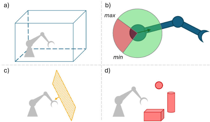
Fig. 4 Example for workspace limitations: a) Cartesian constraints, b) Absolute position values, c) Boundary planes, and d) Forbidden volumes
Workspace monitoring can be temporarily deactivated by enabling Rescue Mode, which allows the robot to be released from workspace limits that have already been exceeded, for example to safely recover from an error condition.
3.3.1. Cartesian Constraints
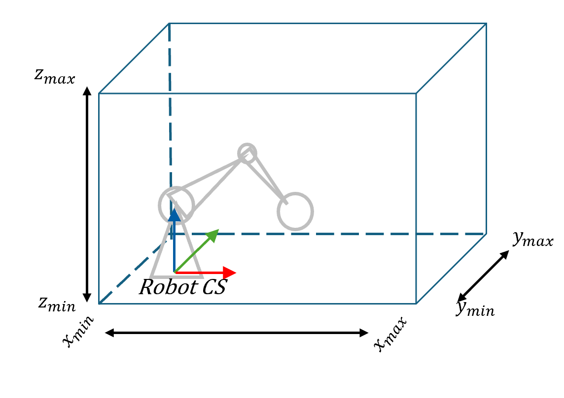
The Cartesian constraints define a cuboidal workspace within the Robot Coordinate System (Robot CS), as shown in in Fig. 5, and the robot is required to remain inside this workspace at all times. These constraints are specified in the Robot CS by the minimum and maximum values along each axis. If the robot moves outside this defined workspace, an error is triggered to prevent unsafe operation. All Cartesian constraints are can be configured as described in Workspace Data.
OPC UA
With the OPC UA command SetCartesianConstraints (NodeId: 100203) the Cartesian constraints can be set.
The command is located under Robot/Commands/ (NodeId: 100003). The current values are published under
Robot/CartesianConstraints with NodeId 100002. As mentioned before the Cartesian constrains are
are saved in the data files, as defined in Workspace Data.
3.3.2. Joint Angle
Joint angle limitations are part of the workspace constraints and are monitored with respect to absolute position values, see Fig. 4 b), as well as relative constraints between axes. Detailed information on the configuration of absolute axis limits is provided in User defined limits. The definition of the axes parameter is given in Axes and Axes Position Limits Relative.
3.3.3. Boundary Planes
A boundary plane is defined by three linearly independent points and can be freely oriented within the workspace. The robot is required to remain on a specific side of the plane, which is determined by an additional reference point. The reference point must not lie on the plane itself (see Fig. 6).
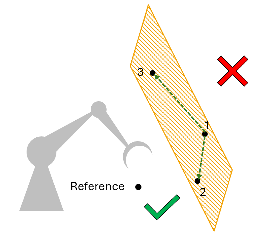
Fig. 6 Schematic example of boundary planes with reference points
Boundary planes can be created or deleted, and they can be activated or deactivated as needed. If the robot violates the defined boundary plane, an error is triggered to prevent unsafe operation.
Note
Currently, boundary planes are only saved at runtime, which means they must be re-created after a system restart. Support for persistent saving of boundary planes to a configuration file is currently in development.
OPC UA
Commands to manage boundary planes are located at Robot/Commands/BoundaryPlanes/ (NodeId: 100220).
Note
Currently, OPC UA does not provide an overview of the defined planes.
3.3.4. Forbidden Volumes
Forbidden volumes are used to define spatial regions that the robot is not allowed to enter. A cuboid forbidden volume is defined by a transformation from the Robot Coordinate System (Robot CS) to a dedicated Cuboid Coordinate System (Cuboid CS), as well as by the edge lengths of the cuboid. A sphere is defined by its center point and radius, while a cylinder is defined by a cap point, a bottom point, and a radius. A schematic example of forbidden volumes is shown in Fig. 7.
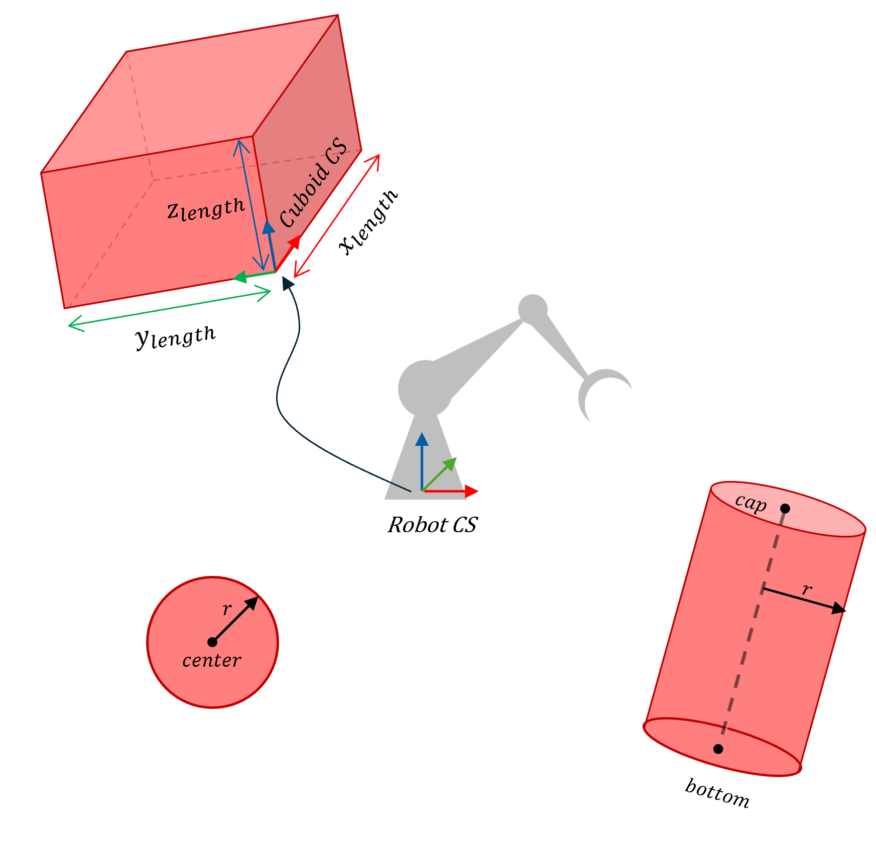
Each forbidden volume can be created or deleted and can be activated or deactivated as required. If the robot enters a forbidden volume, an error is triggered to prevent unsafe operation.
Note
Forbidden volumes are currently saved only at runtime, which means they must be re-created after a system restart. Persistent storage of forbidden volumes in a configuration file is currently under development.
OPC UA
Commands to manage boundary planes are located at Robot/Commands/ForbiddenVolumes/ (NodeId: 100230).
Note
Currently, OPC UA does not provide an overview of the defined volumes.
For more information please check the description in the OPC UA server itself.
3.3.5. Collision Model
The robot structure is approximated by several cylinders, spheres, and capsules, which together form the collision model. This collision model is defined in the robot configuration file and cannot be modified during runtime. Since not all collision volumes are able to collide with each other, only specific collision pairs are monitored. Each collision pair consists of two collision volumes for which collision checking is enabled. This is defined in the config files under Collision Model of the Robot.
The collision model of the robot can be extended to include the attached tool. In this case, the tool collision model and the corresponding collision pairs are defined in the tool configuration file and are considered during collision monitoring. Fore more information see Collision Model of the Tool and Tool Data.
Example: Collision Model for voraus industrial robot
As mentioned earlier, the collision model is composed of multiple collision volumes that approximate the entire robot structure. In the case of the voraus industrial robot, these collision volumes are represented by cylinders.
All cylinders positions are defined in a Denavit–Hartenberg (DH) coordinate system and are updated on each control cycle. Each cylinder is defined by a top and bottom point (x,y,z) [m], a radius [m], and a unique name. For the voraus industrial robot (without tool), the structure is represented by nine cylinders, as shown in the Fig. 8.
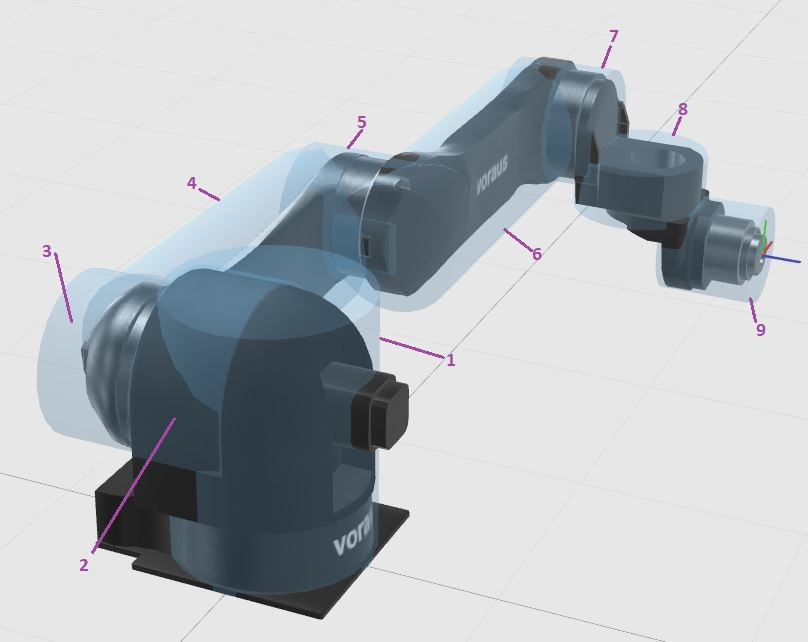
Certain parts of the voraus industrial robot can collide with each other at specific points. The most likely collisions occur between:
base (1) and
upper arm (6), wrist (7 & 8), and hand (9)
upper arm (6) and hand (9)
These defined collision pairs are monitored during operation to ensure safe movement of the robot.
3.3.6. Continuous Jogging
During continuous jogging, the robot automatically reduces its speed as soon as it approaches a workspace restriction in order to prevent a violation. In contrast, programmed motion commands do not require speed reduction, as their trajectories are already known and verified during path pre-interpolation.
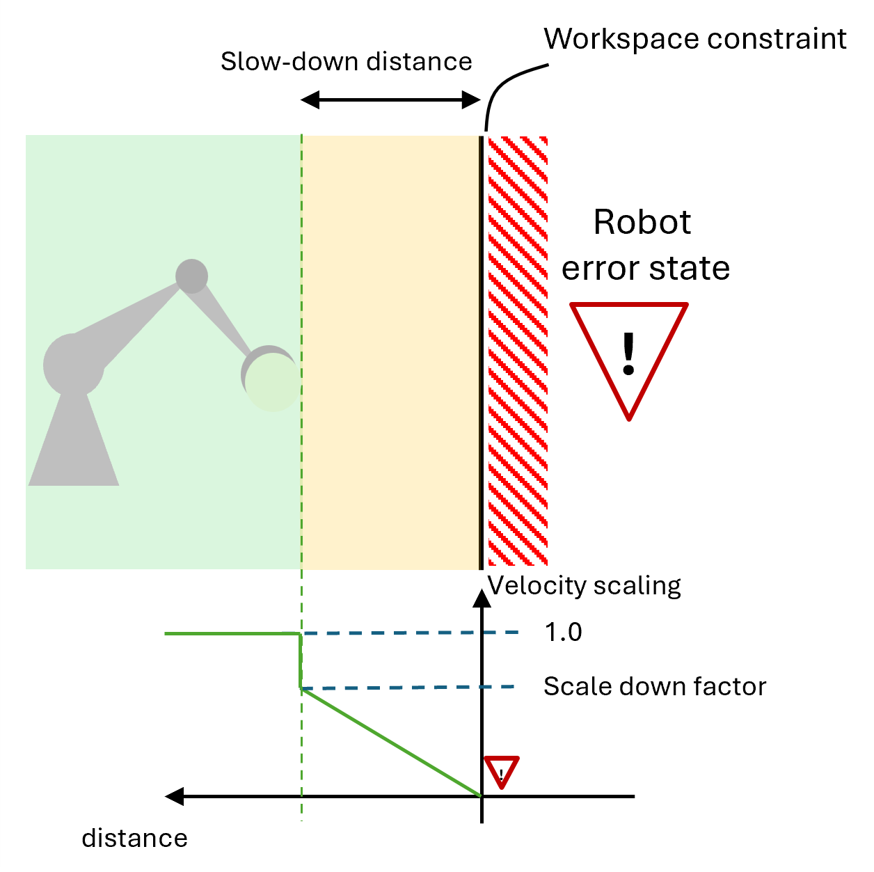
Fig. 9 Schematic example of boundary planes with reference points
To support safe manual operation, an additional speed scaling mechanism is applied during continuous jogging. The speed is dynamically increased or decreased depending on the robot’s distance to the workspace constraints and the direction of motion. The robot’s motion is gradually reduced when it approaches a defined slow-down distance from the limits. A schematic overview of this areas is given in Fig. 9. Movements that lead away from workspace limitations are not affected by this speed scaling, even if they are executed within the slow-down distance.