
4.6. Collision Model
The collision model is a core collision-avoidance feature of the voraus Robot Control. It approximates the physical robot structure using geometric primitives (cylinders, capsules, and spheres) and monitors, in every voraus Robot Control cycle, the distances between defined collision pairs (self-collision) as well as the distances between the collision model and the configured workspace boundaries (Cartesian Constraints, Boundary Planes, and Forbidden Volumes, see Workspace Monitoring). The same checks are also performed ahead of time during path pre-interpolation, so that a motion violating a collision pair or a workspace boundary is rejected before execution. This chapter explains how users can customize and create their own collision models for robots integrated into the voraus Robot Control.
For a detailed description of the collision model parameters and their schema, see Collision Model of the Robot. For an overview of how the collision model is used in workspace monitoring, see Collision Model. The collision model described here covers the robot structure only. Collision volumes for an attached tool are configured separately in the tool configuration file; see Collision Model of the Tool.
Note
The collision model is part of the robot configuration file (a config file). Config files cannot be modified during runtime and are loaded at startup. For more details on file management, see File Management.
4.6.1. How to Customize a Robot Collision Model
The collision model is defined in the robot configuration JSON file located in ${VORAUS_CONFIG_DIR}/robots/.
To customize or create a collision model, you need to:
Identify the robot geometry: Determine the physical dimensions and shape of each link/segment of the robot. Manufacturer datasheets provide the necessary dimensions (link lengths, joint offsets, and segment diameters).
Define collision volumes: Approximate each robot segment with one or more geometric primitives (cylinders, capsules, or spheres). Each volume requires:
A unique
Nameto identify the volume.A
RefCS(Reference Coordinate System) that defines which DH coordinate system the volume is attached toRadiusin meters.Positional parameters (
CapPointandBottomPointfor cylinders/capsules,CenterPointfor spheres).CheckAgainstCartesianConstraintsto indicate whether workspace limits apply to this volume.
Define collision pairs: Specify which pairs of volumes can potentially collide. For each pair, set:
MinDistance: The minimum allowed distance in meters. If violated, an error is raised.ReduceDistance: The distance at which the robot starts to slow down (during jogging) to prevent collision.
Note
The collision model is evaluated in two stages: during path pre-interpolation (to reject invalid motions before execution) and cyclically during operation (to react to unforeseen situations). Both stages check the self-collision pairs as well as the configured workspace boundaries (Cartesian Constraints, Boundary Planes, and Forbidden Volumes, see Workspace Monitoring).
Warning
Every collision volume and every collision pair is evaluated in each voraus Robot Control cycle. Defining an excessive number of collision volumes and collision pairs increases the computational load per cycle and can lead to cycle time violations. Keep the model as simple as possible: use the minimum number of volumes required to approximate the robot structure, and only define collision pairs for volumes that can physically reach each other.
Note
The collision model should be a conservative approximation. Volumes should be slightly larger than the actual robot segments to ensure collisions are detected before physical contact occurs. However, overly large volumes may unnecessarily restrict the robot’s workspace.
4.6.2. Example: Collision Model for KUKA KR 10 R900-2
The KUKA KR 10 R900-2 is a 6-axis industrial robot with a reach of 900 mm and a payload of 10 kg. Its collision model in the voraus Robot Control uses 11 cylinders and 19 collision pairs to approximate the robot structure.
The robot’s kinematic chain is described by DH parameters with the following key link lengths:
Base height (d1): 400 mm
Lower arm (a2): 455 mm
Upper arm (d4): 420 mm
Flange (d6): 90 mm
These dimensions, taken from the KUKA KR 10 R900-2 datasheet, determine how the collision volumes are placed relative to the DH coordinate systems.
Collision Volumes
The collision model uses 11 cylinders attached to five moving robot segments, see also Fig. 21:
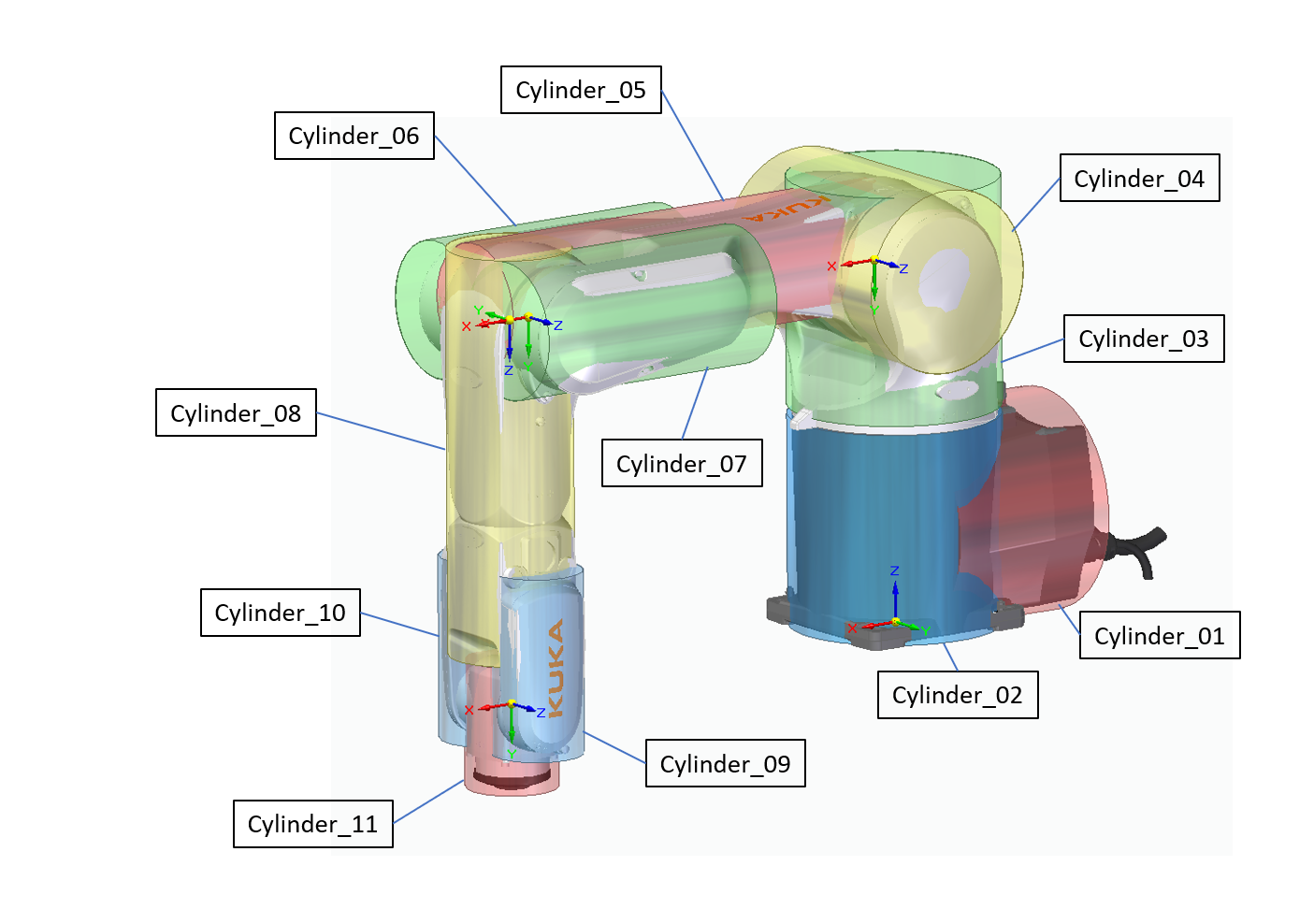
Since each DH coordinate systems is attached to a moving robot segment, they are used to define the position of the collision bodies. The RefCS values in the table above correspond to the DH coordinate systems:
RefCS 0: Robot base coordinate system (fixed),z-axis aligned with joint axis 1RefCS 1: Shoulder, z-axis aligned with joint axis 2RefCS 2: Elbow/lower arm, z-axis aligned with joint axis 3RefCS 3: Elbow/upper arm, z-axis aligned with joint axis 4RefCS 4: Wrist, z-axis aligned with joint axis 5RefCS 5: Wrist, z-axis aligned with joint axis 6RefCS 6: Flange, z-axis aligned with joint axis 6
Collision Pairs
Not all volumes need to be checked against each other. Only volumes that can physically reach each other during operation are defined as collision pairs. The KUKA KR 10 R900-2 uses the following 19 collision pairs:
Note that adjacent volumes (e.g., Base1 and Shoulder1) are not defined as collision pairs because they cannot collide with each other due to their physical proximity in the kinematic chain.
Deriving Collision Volumes from the Datasheet
To create a collision model for the KUKA KR 10 R900-2, the following steps were applied:
Obtain robot dimensions: The KUKA KR 10 R900-2 datasheet provides the key dimensions:
Total height at base: 400 mm (DH parameter d1)
Lower arm length: 455 mm (DH parameter a2)
Upper arm length: 420 mm (DH parameter d4)
Wrist to flange: 90 mm (DH parameter d6)
Approximate link diameters from the mechanical drawings
Map segments to DH coordinate systems: Each collision volume is assigned to the coordinate system of the link it represents. For example, the lower arm cylinders are assigned to
RefCS 2(the DH frame after joint 2), so they move with the lower arm.Define cylinder endpoints: The BottomPoint and CapPoint are chosen to span the entire length of each segment with some margin. For example, LowerArm1 spans from \([0.07, -0.02, 0.0]\) to \([-0.45, -0.02, 0.0]\) in
RefCS 2, covering the full 455 mm lower arm link plus some overlap at the joints.Choose radii conservatively: The radius of each cylinder should be slightly larger than the actual cross section of the robot at that point. For example, the lower arm has a radius of 70-75 mm, which envelops the physical arm profile with some safety margin.
Use multiple volumes per segment where needed: Complex geometries (like the lower arm or upper arm) are approximated with multiple cylinders oriented in different directions to better cover the actual shape.
4.6.3. Best Practices
Start conservative: Use larger volumes initially and refine them if they overly restrict the workspace.
Validate with jogging: After defining the collision model, jog the robot through its workspace and verify that collision warnings/stops occur at appropriate distances.
Consider tool collisions: Remember that tool collision volumes can be defined separately in the tool configuration file (see Collision Model of the Tool).
MinDistance vs. ReduceDistance: Set
ReduceDistancelarger thanMinDistance.ReduceDistancetriggers speed reduction during jogging;MinDistancetriggers a hard stop/error. Typical values areMinDistance= 0.01 m andReduceDistance= 0.10–0.15 m.Adjacent links: Do not define collision pairs for volumes attached to adjacent links, as they will always be close to each other and would trigger false alarms.