
5.4. Circular (CIRC)
The circular (CIRC) command moves the robot’s tool center point (TCP) from its start pose to a specified target pose along a circular path in Cartesian space.
The motion is planned in Cartesian space. The path velocity and acceleration are specified independently for translation and rotation. The starting point of the arc is always the current pose of the robot or the target point of the previous command and is set automatically.
CIRC commands are well-suited for tasks that require the TCP to follow a curved, repeatable path, such as dispensing or welding along rounded contours, or moving around obstacles on a defined arc.
Note
The robot must be in READY or ACTIVE state to accept CIRC motion commands. See section
Prerequisites for command acceptance for more details on prerequisites for motion command acceptance.
5.4.1. Arc Definition Modes
An arc through Cartesian space cannot be defined by a start and a target pose alone, because infinitely many circles pass through two points. A third piece of geometric information is therefore required. The CIRC command provides three modes, each defining the arc in a different way.
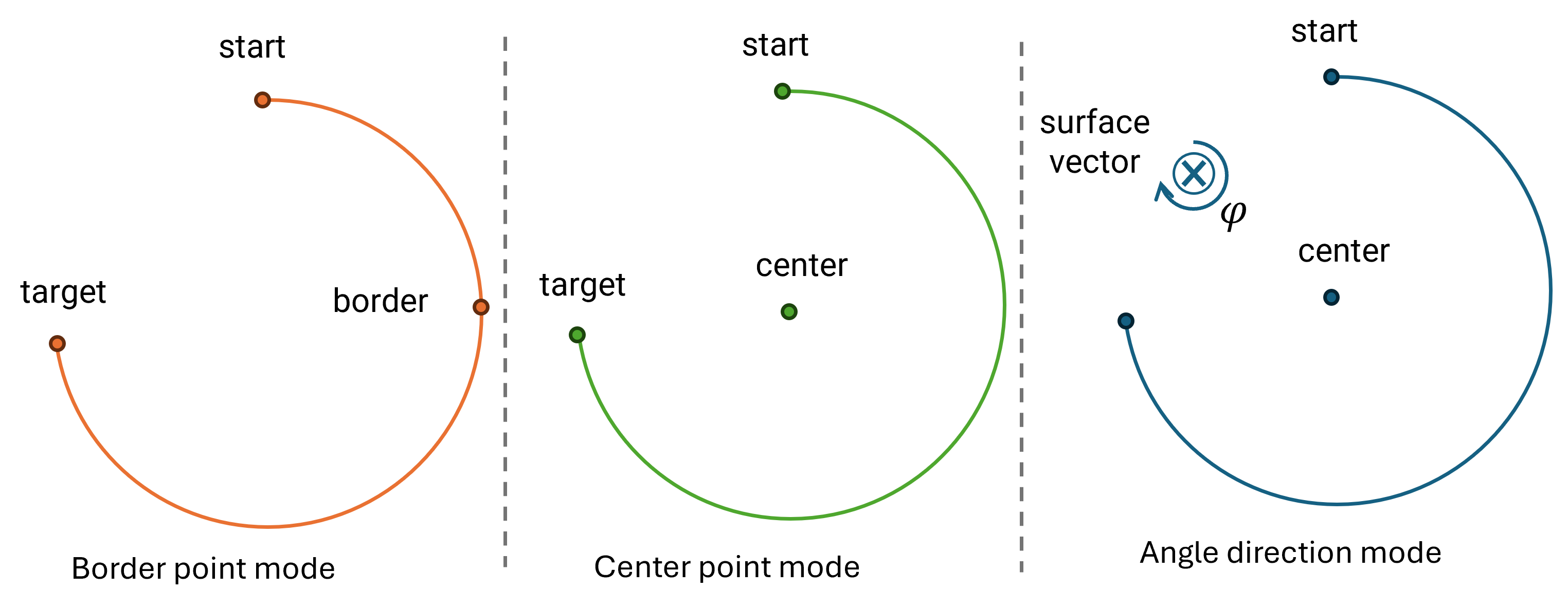
Fig. 24 Definition of a circular arc in border point, center point, and angle direction mode
Fig. 24 illustrates the three arc definition modes geometrically, while Table 75 lists the corresponding commands and the parameters that define the arc in each mode.
All three modes share the same common parameters (path velocities and accelerations, blending, orientation interpolation, coordinate systems). They differ only in the parameters that define the geometry of the arc. See Parameters for the full list.
5.4.2. Parameters
The CIRC command accepts the parameters in the sections listed below. The common parameters apply to all three arc
definition modes, see Table 75. The mode-specific parameters define the geometry of the arc and
depend on the selected command (MoveCircBorder see Table 77,
MoveCircCenter see Table 78, MoveCircAngle see
Table 79).
Common Parameters
Parameter |
Type |
Default |
Description |
|---|---|---|---|
|
Double |
|
Maximum translational path velocity in \([\mathrm{m/s}]\). If the start and target poses differ, this
must be > |
|
Double |
|
Maximum translational path acceleration in \([\mathrm{m/s^2}]\). If the start and target poses differ,
this must be > |
|
Double |
|
Maximum rotational path velocity in \([\mathrm{rad/s}]\). Only used if |
|
Double |
|
Maximum rotational path acceleration in \([\mathrm{rad/s^2}]\). Only used if |
|
Boolean |
|
If |
|
Integer (enum) |
|
Defines how the TCP orientation is interpolated along the path, see Orientation Interpolation. |
|
Boolean |
|
If |
|
Boolean |
|
If |
|
Double |
|
Blending radius. Interpretation depends on |
|
Integer (enum) |
|
Specifies how the blending parameter is interpreted: |
|
Integer (enum) |
|
Specifies which frame arrives at the target, see Table 2. Note Limitation: for CIRC commands this parameter is currently ignored - the Tool CS always arrives at the target, regardless of the specified value. |
|
Unsigned integer |
|
Unique identifier for tracking the command. See Command Tracking. |
|
Boolean |
|
If |
Border Mode Parameters
In border mode, MoveCircBorder, the arc is defined by the start pose, the target pose, and an
additional point on the arc.
Parameter |
Type |
Default |
Description |
|---|---|---|---|
|
Array of double |
— |
Target pose. Interpretation depends on |
|
Integer (enum) |
|
Coordinate system in which the target is specified. See Coordinate Systems. |
|
Array of double |
— |
A point lying on the arc between start and target. Only its position is used; any orientation component is
ignored. The interpretation depends on Note Specifying the border point in joint space is not recommended. Use absolute Cartesian coordinates instead. |
|
Integer (enum) |
|
Coordinate system in which the border point is specified. See Coordinate Systems. |
Center Mode Parameters
In center mode, MoveCircCenter, the arc is defined by the start pose, the target pose, and the center
point of the circle.
Parameter |
Type |
Default |
Description |
|---|---|---|---|
|
Array of double |
— |
Target pose. Interpretation depends on |
|
Integer (enum) |
|
Coordinate system in which the target is specified. See Coordinate Systems. |
|
Array of double |
— |
The center point of the circle. Only its position is used; any orientation component is ignored. The
interpretation depends on Note Specifying the center point in joint space is not recommended. Use absolute Cartesian coordinates instead. |
|
Integer (enum) |
|
Coordinate system in which the center point is specified. See Coordinate Systems. |
|
Boolean |
|
Defines the travel direction around the circle. |
Angle Mode Parameters
In angle mode, MoveCircAngle, the arc is defined by the start pose, the center point, a rotation axis and a
swept angle. The target pose is not specified directly; instead, the target orientation is provided separately.
Parameter |
Type |
Default |
Description |
|---|---|---|---|
|
Array of double |
— |
The center point of the circle. Only its position is used; any orientation component is ignored. The
interpretation depends on Note Specifying the center point in joint space is not recommended. Use absolute Cartesian coordinates instead. |
|
Integer (enum) |
|
Coordinate system in which the center point is specified. See Coordinate Systems. |
|
Double |
— |
Desired swept arc angle in \([\mathrm{rad}]\), this must be 0 < |
|
Array of double |
— |
Normal vector \([X, Y, Z]\) of the plane in which the arc lies, defined in the robot coordinate system. It acts as the rotation axis about the center point. The vector does not need to have unit length (length 1); it is normalized internally. |
|
Array of double |
— |
Target orientation as Euler angles \([A, B, C]\) in \([\mathrm{rad}]\) (Kardan convention). In angle mode, the center point, surface normal vector and circular angle define the target position only; the target orientation is specified separately by this parameter. |
5.4.3. Coordinate Systems
The TargetReferenceCS parameter defines the coordinate system in which the target pose is specified. Its value
is the numeric OPC UA identifier of the desired coordinate system, as listed in Table 1 in
section Coordinate Systems Overview.
The chosen value determines how the target pose is interpreted:
0(Joint CS): The target is specified as joint angles in \([\mathrm{rad}]\). The corresponding Cartesian target pose is derived via forward kinematics before path planning.1–19(Cartesian frames): The target is specified as a Cartesian pose relative to the selected frame, e.g. the Robot CS (1), Tool CS (2), Camera CS (3), or one of the User CS (4–19), and is used directly for path planning.
The geometry points (BorderPointReferenceCS, CenterPointReferenceCS) can be specified independently of
TargetReferenceCS, but do not support Camera CS (3). The surface normal vector of MoveCircAngle
is always interpreted in the robot coordinate system.
Regardless of the selected coordinate system, the motion planner performs inverse kinematics along the arc to determine the corresponding joint poses at each interpolation step.
For the full list of available coordinate systems, their identifiers, and detailed descriptions, see Coordinate Systems Overview.
5.4.4. Target Coordinates
How the target pose is reached depends on the coordinate system in which it is specified. This applies to the border
point (MoveCircBorder) and center point (MoveCircCenter) modes, where the target pose is given via
TargetReferenceCS. In angle direction mode (MoveCircAngle), the end of the arc is instead defined by
the swept angle and a separately specified target orientation, not by a target coordinate system.
Cartesian Coordinates
When the target is specified in a Cartesian coordinate system, the TCP moves along the circular arc to the target pose. The specified Cartesian target pose is reached exactly as given.
Note
The same orientation can be represented by different angles. Consequently, the resulting orientation angles may differ from the specified value, but they represent the same orientation.
Joint Coordinates
When the target is specified in the joint coordinate system (TargetReferenceCS = 0), the given joint
angles are converted into a Cartesian target pose. The Cartesian pose results from the forward kinematic which
calculates the flange pose. Afterwards, the flange to tool transformation is added.
Since the robot then moves along the circular arc to that Cartesian pose, the exact joint configuration at the target cannot be guaranteed. It depends on the robot’s start configuration and rotation settings, see Orientation Interpolation.
5.4.5. Motion Profile
The CIRC motion profile is computed in Cartesian space, analogous to the LIN motion profile. The TCP follows an arc from the start to the target pose instead of a straight line. As with LIN, translation and orientation are interpolated by separate motion profiles that are synchronized to a common duration, so that both reach the target simultaneously.
Translation: Interpolation along the path coordinate
The arc lies on a circle with a fixed radius \(r\) in \([\mathrm{m}]\) and center point, which are derived from the selected arc definition mode. As for Linear (LIN) motions, the robot does not interpolate the individual Cartesian axes \(X\), \(Y\) and \(Z\) independently. Instead, it interpolates along the path itself, using a scalar path coordinate \(s(t)\) that measures progress along the arc. The translational path length corresponds to the arc length \(L = r \cdot \varphi\), where \(\varphi\) is the swept arc angle in \([\mathrm{rad}]\). Fig. 25 illustrates this path coordinate.
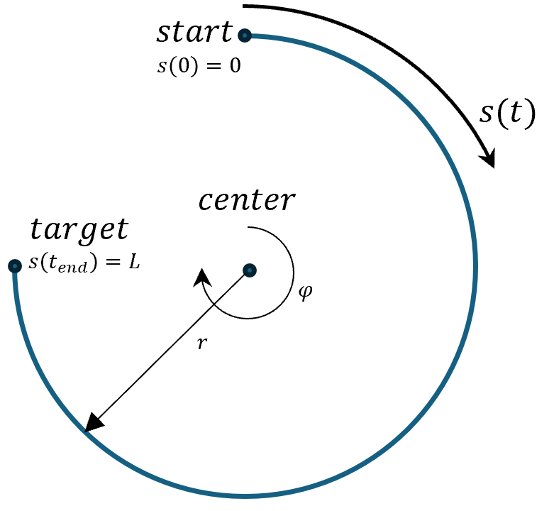
Fig. 25 Schematic of the CIRC path coordinate \(s(t)\) along the circular arc from start to target pose
The configured translational velocity and acceleration are applied to this path coordinate in the same way as for LIN - that is, they limit the speed and acceleration of the TCP along the arc, not of the individual \(X\), \(Y\) or \(Z\) components.
Rotation: SLERP between orientations
Analogous to LIN, the orientation is interpolated by spherical linear interpolation (SLERP), driven by its own normalized coordinate to which the configured rotational path velocity and acceleration are applied; see Lin motion profile for details on the interpolation and Orientation Interpolation for the available rotation types.
Common duration
The overall motion duration is determined by the slower of the two components (translation or rotation), ensuring that both the position and the orientation reach the target simultaneously.
Note
The configured path velocities and accelerations are treated as upper bounds. If a requested value exceeds the active robot or safety limit, it is reduced to that limit (a warning is logged) rather than rejected; the motion then executes at the reduced value. Consequently, the robot may move slower than requested.
5.4.6. Orientation Interpolation
The orientation of the TCP during the CIRC motion is interpolated between the start and target orientation. The same rotation types as for LIN motions are available, see LIN orientation interpolation.
5.4.7. Blending
CIRC commands support blending with previous adjacent motion commands, enabling smooth transitions without stopping at intermediate poses. For a detailed description of the Cartesian blending behavior, see Cartesian Blending.
To enable blending, set WithBlending to true and specify a BlendingParameter greater than
0.0. The blending parameter can be specified either as a percentage of the shorter adjacent segment
(BlendingType = 0) or as an absolute distance in meters (BlendingType = 1).
The transition between consecutive motion segments is continuous and smooth, so the robot does not stop at the intermediate pose.
Note
Blending between a PTP motion and a circular motion is currently not supported and will be implemented in a future release.
5.4.8. Error Conditions
Error conditions are reported at two distinct stages. It is important to distinguish between them, because they require different handling by the client application. See also Prerequisites for command acceptance for general prerequisites that apply to all motion commands.
Rejected on Submission
The following conditions cause the CIRC command to be not accepted - it does not enter motion planning and the robot keeps its current state. Depending on the condition, the command is either not queued or silently discarded:
The robot is not in
READYorACTIVEstate.The motion command queue is full. See Queue Overview for the queue capacity and how to handle a full queue.
The general prerequisites in Prerequisites for command acceptance (no stop in progress, position streaming inactive, no conflicting command type) are also checked before the command is accepted.
Errors during Motion Planning
The following conditions are not detected when the command is submitted. The command is accepted into the queue and only fails later, once it is processed by the motion planner. Such a failure raises an error and stops motion execution rather than rejecting the enqueue:
The geometry of the arc cannot be determined, for example when:
the start and target poses are identical (border and center mode),
the start and center poses are identical (center and angle mode),
the target and center poses are identical (center mode),
the border and start/target poses are identical (border mode),
the distance between the start and center pose and the distance between the target and center pose are not equal (center mode),
the three defining points are collinear and therefore do not define a unique circle,
an invalid rotation axis (surface normal vector) is specified (angle mode).
The start and target poses differ and
PathVelocityTranslationis not greater than0.0.The start and target poses differ and
PathAccelerationTranslationis not greater than0.0.The
RotationTypeis1(Standard), the start and target orientations differ, andPathVelocityRotationorPathAccelerationRotationis not greater than0.0.An invalid coordinate system value or an invalid blending type is specified.
The target pose or the resulting arc violates configured axis position limits (after inverse kinematics).
The motion results in a singularity or the inverse kinematics cannot be solved along the arc.