
5.2. Point-to-Point (PTP)
The point-to-point (PTP) command moves the robot from its start pose to a specified target pose. The motion is planned and executed in joint space, meaning each axis moves independently according to its own velocity and acceleration limits. All axes are time-synchronized so that they start and finish simultaneously.
Unlike Linear (LIN) or Circular (CIRC) motions, a PTP command does not define an explicit Cartesian path for the tool center point (TCP). The resulting TCP path in Cartesian space depends on the individual axis motions and is generally not a straight line.
PTP commands are well-suited for fast repositioning when the exact Cartesian path between start and target is not critical.
On the OPC UA interface, a PTP motion is commanded via the MoveJoints method.
Note
The robot must be in READY or ACTIVE state to accept PTP motion commands. See section
Prerequisites for command acceptance for more details on prerequisites for motion command acceptance.
5.2.1. Parameters
The PTP command contains the following parameters:
Parameter |
Type |
Default |
Description |
|---|---|---|---|
|
Array of double |
— |
Target pose. Interpretation depends on |
|
Integer (enum) |
|
Coordinate system in which the target is specified. See Coordinate Systems in the section below or the section Coordinate Systems Overview for more information. |
|
Double |
|
Scaling factor for maximum axis velocities. Valid range: |
|
Boolean |
|
If |
|
Boolean |
|
If |
|
Double |
|
Blending radius as a percentage ( |
|
Array of integer |
|
Optional joint configuration vector for inverse kinematics disambiguation when |
|
Integer (enum) |
|
Specifies which coordinate system arrives at the target coordinate: |
|
Unsigned integer |
|
Unique identifier for tracking the command. See Command Tracking. |
|
Boolean |
|
If |
5.2.2. Coordinate Systems
The TargetReferenceCS parameter defines the coordinate system in which the target pose is specified. Its value
is the numeric OPC UA identifier of the desired coordinate system, as listed in Table 1 in
section Coordinate Systems Overview.
The chosen value determines how the target pose is interpreted:
0(Joint CS): The target is specified directly as joint angles in \([\mathrm{rad}]\) (rotational joints) or displacements in \([\mathrm{m}]\) (prismatic joints). No inverse kinematics is required.1–19(Cartesian frames): The target is specified as a Cartesian pose relative to the selected coordinate system, e.g. the Robot CS (1), Tool CS (2), Camera CS (3), or one of the User CS (4–19). The pose is resolved into joint space through inverse kinematics.
For the full list of available coordinate systems, their identifiers, and detailed descriptions, see Coordinate Systems Overview.
5.2.3. Target Coordinates
How the target pose is reached depends on the coordinate system in which it is specified.
Joint Coordinates
When the target is specified in the joint coordinate system (TargetReferenceCS = 0), each axis moves
exactly to the given angle. The target joint positions are reached precisely as specified, without any inverse
kinematics.
Cartesian Coordinates
When the target is specified in a Cartesian coordinate system, the same Cartesian pose can usually be reached by several different joint configurations (for example, elbow up vs. elbow down). The motion planner selects the target joint configuration according to the following priorities:
Explicit configuration (if provided). If a configuration is specified via the
ConfigVectorparameter, that configuration is used. See Coordinate Systems and theConfigVectorentry in Table 72 for details.Start configuration. If no configuration is specified, the planner tries to keep the robot’s current (start) configuration, provided the target can be reached with it while staying within the axis limits. This is usually the most intuitive result, as it avoids unnecessary reconfiguration.
Shortest path. If neither of the above applies, the planner evaluates all reachable configurations that stay within the axis limits and selects the one that results in the shortest motion.
Note
For priority 3, “shortest motion” is determined per configuration by the single axis that has to travel the largest distance (the leading axis). Among all reachable configurations, the planner then chooses the one whose leading axis travels the smallest distance.
Note
If the target pose cannot be reached by any valid configuration within the axis limits, the PTP command is not accepted. See Prerequisites for command acceptance and the error conditions listed for the PTP command.
5.2.4. Motion Profile
The PTP motion profile is computed individually for each axis with the configured velocity and acceleration limits (see Limitations). All axis profiles are time-synchronized: the axis with the longest travel time determines the overall motion duration, and all other axes are scaled to match.
Fig. 22 illustrates this for two axes (\(q_1\) and \(q_2\)). Before synchronization (left), each axis would reach its target as fast as its own limits allow, finishing at different times. After synchronization (right), the faster axis is slowed down - its peak velocity \(v_{max}\) and acceleration \(a_{max}\) are reduced - so that both axes start and stop simultaneously at \(t_{sync}\).
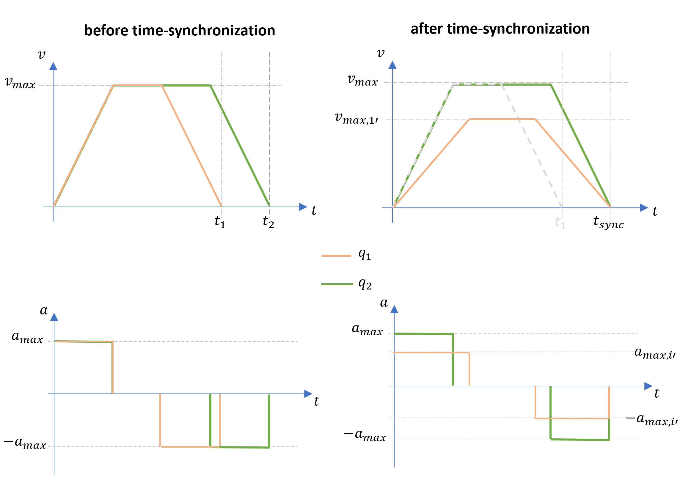
Fig. 22 Schematic of the PTP motion profile before and after time synchronization of two axes
The VelocityScaling parameter allows reducing the maximum axis velocities proportionally. For example, a
value of 0.5 limits each axis to 50% of its configured maximum velocity. This affects the overall motion
duration accordingly and may also change the resulting Cartesian path.
Note
Acceleration limits are not configurable per command. They are determined by the robot’s configured axis acceleration limits.
5.2.5. Blending
PTP commands support blending with adjacent motion commands, enabling smooth transitions without stopping at intermediate pose. For a detailed description of the PTP blending behavior, see PTP Blending and PTP-LIN Blending.
To enable blending, set WithBlending to true and specify a BlendingParameter greater than
0.0. The blending parameter defines the blending radius as a percentage of the shorter adjacent segment, with
the exception of PTP blending in the same direction, see PTP Blending in Same Direction.
5.2.6. Error Conditions
Error conditions are reported at two distinct stages. It is important to distinguish between them, because they require different handling by the client application. See also Prerequisites for command acceptance for general prerequisites that apply to all motion commands.
Not Accepted
The following conditions cause the PTP command to be not accepted - it does not enter motion planning and the robot keeps its current state. Depending on the condition, the command is either not queued or silently discarded:
The robot is not in
READYorACTIVEstate.The motion command queue is full. See Queue Overview for the queue capacity and how to handle a full queue.
The general prerequisites in Prerequisites for command acceptance (no stop in progress, position streaming inactive, no conflicting command type) are also checked before the command is accepted.
Errors during Motion Planning
The following conditions are not detected when the command is submitted. The command is accepted into the queue and only fails later, once it is processed by the motion planner. Such a failure raises an error and stops motion execution rather than rejecting the enqueue:
The
ConfigVectoris invalid (wrong size, or contains values other than+1or-1) when a Cartesian coordinate system is selected and a configuration vector is provided.The
VelocityScalingvalue is outside the valid range (0.01–1.0).An invalid coordinate system value is specified.
The target pose violates configured axis position limits.