
2.3.1. Installation for the voraus.core
Note
The following chapter describes the installation of the voraus.core software. Please select the section corresponding to your setup, whether it is a physical robot or a virtual instance.
Installation for the voraus.core in a virtual environment
The following chapter describes the installation of the voraus.core in a virtual environment.
Note
This section covers the installation and management of virtual evaluation systems. The virtual systems are only for showcasing purposes and not capable of controlling real robots.
The voraus.core is delivered as a Docker image and can be executed on Docker-capable systems.
Prerequisites
The following software must be installed and configured on your machine before you can run the voraus.core.
Note
The software runs exclusively on x86 systems, ARM systems are not supported.
Windows WSL
Windows Subsystem for Linux v2 (WSL 2) must be enabled on your computer.
You can find more information in the Microsoft documentation.
Docker
Install Docker on your machine according to the official documentation.
Note
- If you are using Windows, make sure you are using:
the WSL 2 backend and not the Hyper-V backend.
Powershell instead of the legacy CMD terminal for all Docker terminal commands in this documentation.
You can check whether Docker is installed and configured properly by entering the following command into your Terminal.
docker info
If the command exits successfully, i.e. displays information about the Docker installation, everything is installed correctly.
WIBU CodeMeter User Runtime
The voraus.core is protected and licensed with WiBu CodeMeter. In order to run the software it is necessary to install the CodeMeter User Runtime which can be downloaded from the WiBu Support Page or installed as a Linux package from the WiBu Package Repository.
For Windows Users
Select your operating system in the dropdown and download the newest version of the CodeMeter User Runtime.
Run the installer and follow the instructions.
Note
Make sure CodeMeter is configured as a Network Server during the installation.
If you already have CodeMeter installed and want to configure it as a Network Server, follow the instructions in the WiBu support section.
Further information and support during installation can also be found in the WiBu user guide at any time. Go to the support section of WiBu and select the CodeMeter Runtime Installation Guide.
For Linux (Debian and Ubuntu) Users
Linux distributions favor so-called package managers for a centralized distribution of software packages and
their potential updates in a similar fashion to an app store for smartphones.
The package manager for Debian, Ubuntu, and several other Linux distros is called apt.
It allows voraus - as the package’s maintainer - to provide digitally signed versions of it
and install/update them as requested by the user.
The two steps to install the package repo for Ubuntu and Debian can be found here.
Afterwards installing the latest WiBu CodeMeter Runtime is a simple apt call:
sudo apt install codemeter-lite
Updating the package subsequently happens along with all other package updates:
sudo apt update
sudo apt upgrade
Installation for the voraus.core with FANUC robots
The following chapter describes the installation of the voraus.core with FANUC robots.
Setting up the FANUC robot for usage with the voraus.core
Warning
When using, operating and interacting with a FANUC robot, always obey to the instructions of the original FANUC manual.
The following sections assume that the FANUC robot is set up and can be moved with the teach pendant and the default FANUC cabinet software. If the robot is not set up yet, please follow the official FANUC documentation.
In order to connect the voraus.core to a FANUC system, the FANUC cabinet has to be prepared first.
Checking installed software options
The voraus.core needs the activated FANUC software module R912 - Remote Motion Interface to communicate with the control cabinet. In order to check that it is activated, interact with the teach pendant:
Press: MENU → 0: NEXT → 4: STATUS → 2: Version ID.
Press: NEXT → ORDER FI (F3).
Options are listed, click YES for further displaying until you find R912 Remote Motion (Fig. 5).
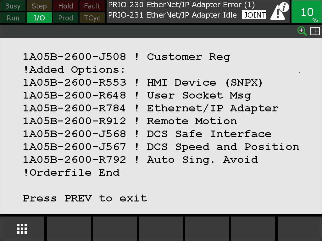
If you do not find R912 Remote Motion, the voraus.core cannot connect successfully. Please contact the FANUC support to buy or install the required software options.
Connecting the robot to the network
The FANUC control cabinet has to be connected to an industrial PC running the voraus.core. This could either be a voraus.ipc with a preinstalled voraus.core or your custom system running the voraus.core.
Warning
Please familiarize yourself with the safety instructions in the FANUC manual. Beware of electric shock. Shut down the robot and ground the control cabinet prior to opening it.
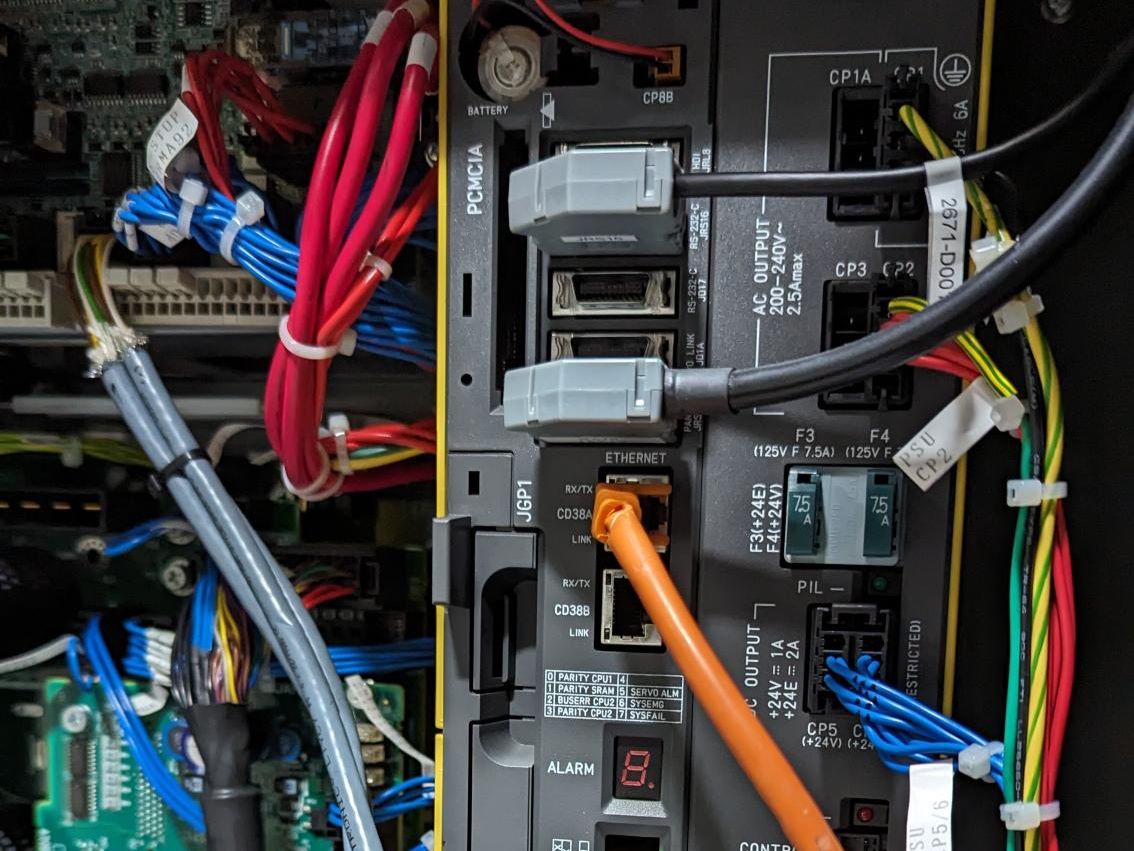
Open the control cabinet and connect the voraus.ipc via Ethernet with port 1 (CD38A) inside the cabinet. Port 1 is marked with the orange cable in Fig. 6.
The network connection has to be configured. Start the robot and navigate on the teach pendant to the network settings via:
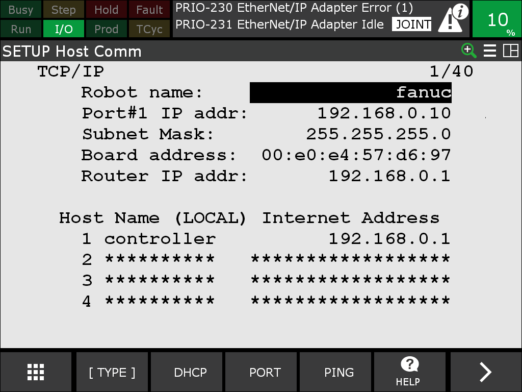
MENU → 6: SETUP → 0: NEXT → 0: NEXT → 1: Host Comm → TCP/IP → ENTER.
Then configure the settings for port 1 according to your network setup. In case you use the voraus.ipc the router IP address has to be 192.168.0.1. For use with a different configuration please contact the voraus support. Fig. 7 shows an example configuration.
Switching to the right operating mode
Since the voraus.core is an external control for the FANUC robot, it can only take control of the robot, if the cabinet is switched to the automatic mode. Hence, instructions can no longer be input via the teach pendant. Switch of the teach pendant by turning the operating mode switch shown in Fig. 8. If the teach pendant displays options to switch the operating mode, select AUTO and enter the PIN. The default PIN is 1111.
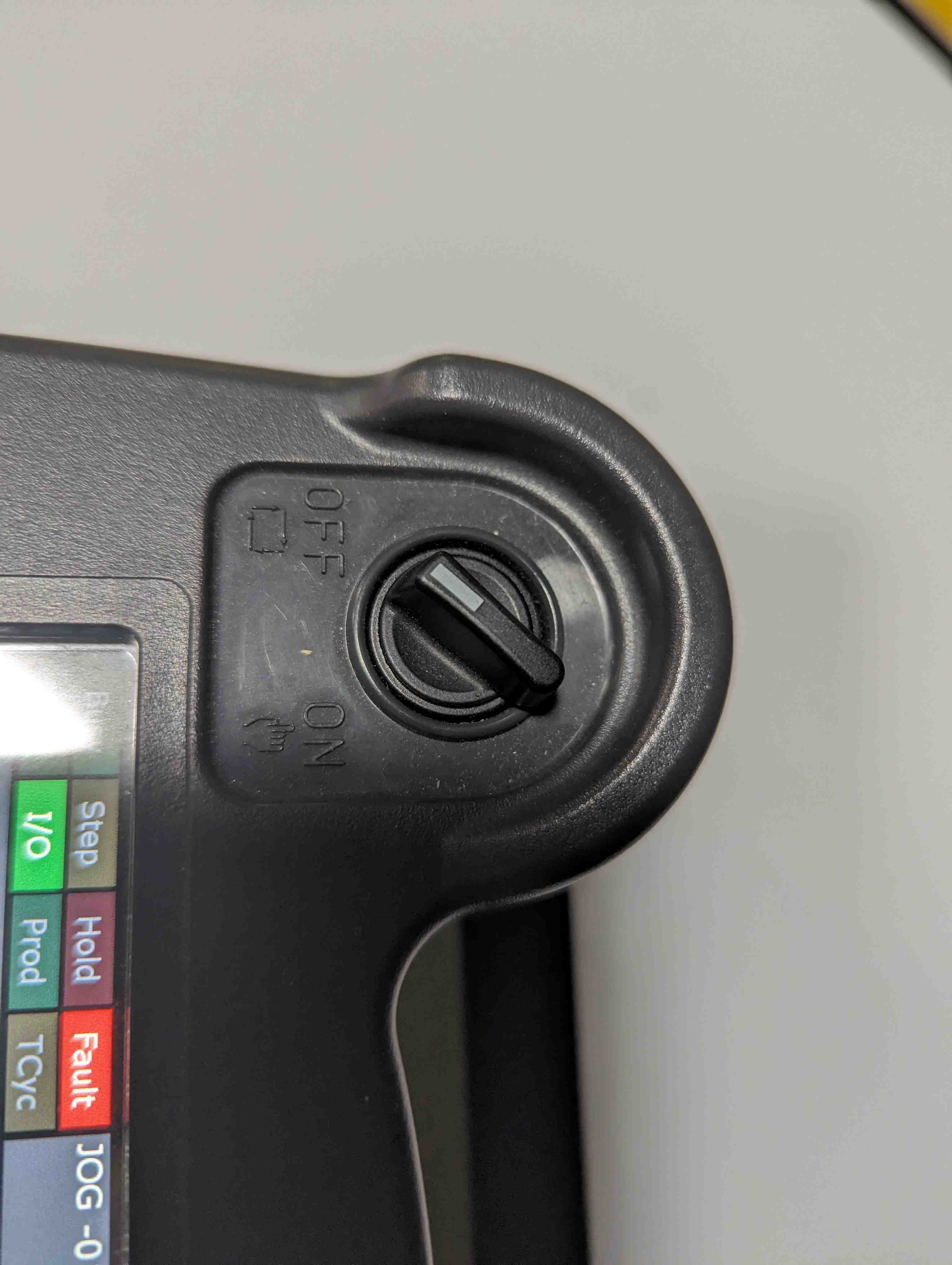
Fig. 8 Switch for toggling between manual and automatic mode
Some FANUC robots may have a key-switch at the cabinet. If there was no option to choose the AUTO mode on the screen, turn the key-switch at the cabinet to AUTO (Fig. 9).
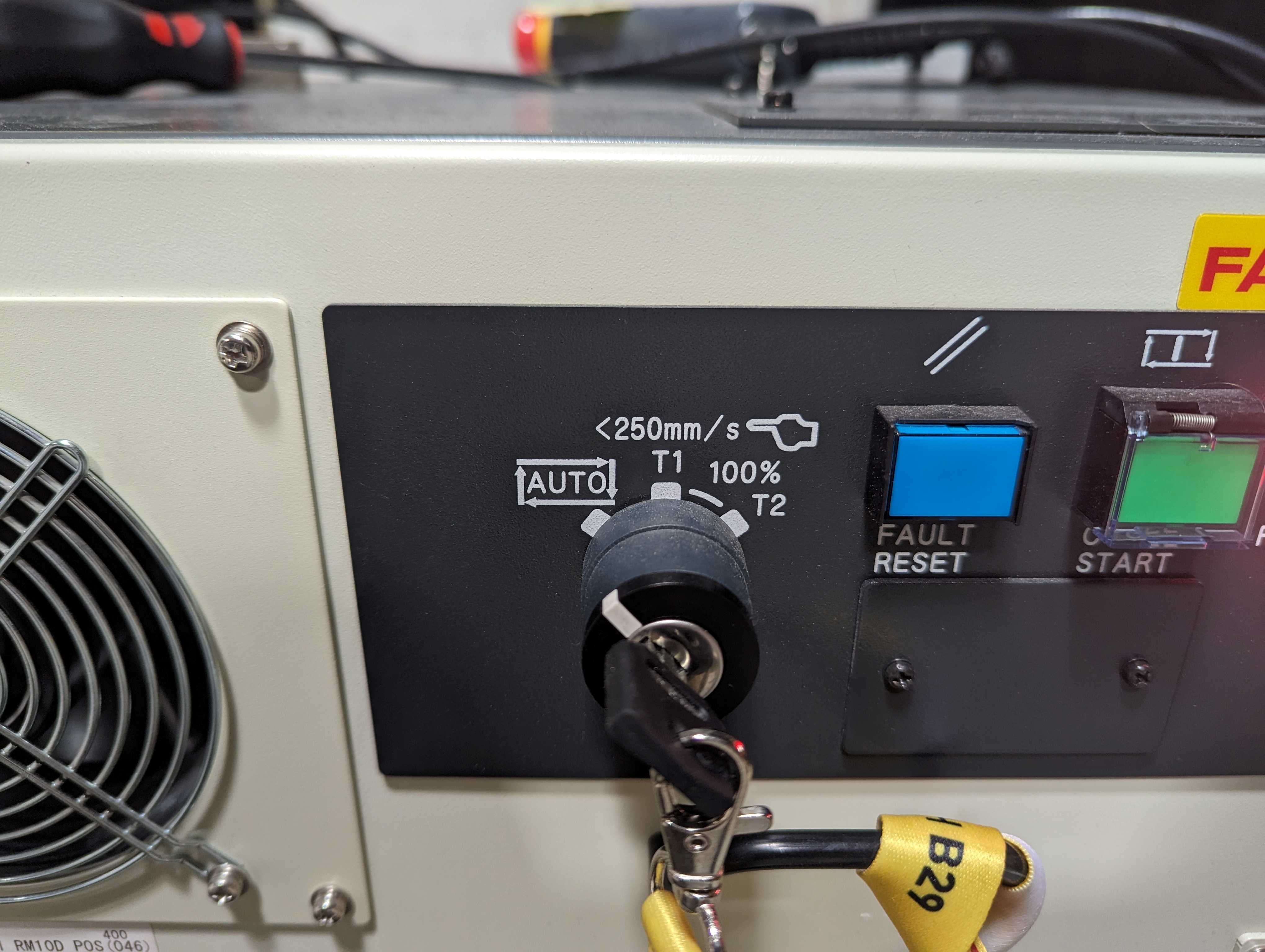
Fig. 9 Key-switch for toggling between manual and automatic mode
Before starting the voraus.core, the FANUC robot should not display any errors. If the teach pendant displays errors, reset them by pressing RESET on the teach pendant. Make sure, the emergency stop is unlocked. The voraus.core can not take control of the robot if the emergency stop on the teach pendant is pressed.
Configuring Automatic Mode to Conform to Manual Mode Limitations according to EN ISO 10218-1
EN ISO 10218-1 defines, that a limited move set with reduced speeds of 250 mm/s shall be used when jogging, teaching, programming and verifying robot programs. The FANUC control cabinet implements an operation mode T1 which conforms to these requirements. However, as previously described, the voraus.core can only take control of the robot, if the cabinet is switched to the automatic mode AUTO.
In order to still conform to EN ISO 10218-1 when teaching robot programs with the voraus.core, the settings of the AUTO mode have to be manually configured to dynamically change the limitations to T1 behavior. The emulated T1 behavior is subsequently called ET1. An external input, e.g., a key switch, or a virtual setting on the controller can then be used to switch between true AUTO mode and ET1. In the following example a virtual setting is used.
To set up ET1 mode, create two SIR (Safe Internal Relay) variables in the safety system.
Navigate on the teach pendant via MENU → 0: NEXT → 6: SYSTEM → 8: DCS → 1 Safe I/O Status:.
Then press ENTER and select F2 DATA → 5: SIR.
Name SIR1 Automatic Mode and SIR2 Movement Allowed as shown in Fig. 10.
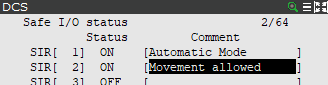
Which signals are used to change the variables is configured in the DCS menu 2 Safe I/O connect. Fig. 11 shows the settings to use. The status SIR[1] - Automatic Mode is changed manually in this example and no input is connected to the cabinet. If an input is used, map an SSI (Safe System Input) with the matching port your switch is connected to.
The status SIR[2] - Movement Allowed combines an enabling device with the current mode SIR[1] - Automatic Mode.
It is possible to use the enabling device of the FANUC teach pendant.
This input can be found at SSI[5].
If an external enabling device is used, map an SSI with the matching port your switch is connected to.

The variables SIR[1] - Automatic Mode and SIR[2] - Movement Allowed can now be used to activate and deactivate limitations. Two limitations are needed. On the teach pendant as before navigate to the DCS menu. Switch to menu entry “6 Cart. speed check” and select the configuration to modify with the [DETAIL] button.
The first configuration shown in Fig. 12 relates to standstill monitoring
and defines a speed limit of zero.
This means, if the robot moves, an SS1 stop is performed immediately.
Take care to change the fields Disabling input to SIR[2] and Stop type to
Stop Category 1.
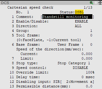
The second configuration shown in Fig. 13 defines a speed limit of 250 mm/s according
to the manual mode at reduced speed in EN ISO 10218-1.
If the robot movement exceeds this speed limit,
an SS1 stop is performed immediately.
Take care to change the fields Disabling input to SIR[1] and Stop type to
Stop Catgeory 1 and Limit to 250.
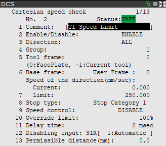
Warning
Test the application of your settings before using the robot.
The setup of ET1 is now complete. Switch to ET1 when programming your application by setting SIR[1] - Automatic Mode to Off (2 Safe I/O connect → SIR[1] → Input1 → OFF). If you want to leave ET1 and switch back to the true AUTO mode, switch SIR[1] - Automatic Mode to On.
Installation for the voraus.core with KUKA robots
The following chapter describes the installation of the voraus.core with KUKA robots.
Setting up the KUKA robot for usage with the voraus.core
Warning
When using, operating and interacting with a KUKA robot, always obey the instructions of the original KUKA manual.
The following sections assume that the KUKA robot is set up and can be moved with the KUKA smartPAD and the default KUKA controller software. If the robot is not set up yet, please follow the official KUKA documentation. Also, it is assumed that the user knows the basic steps on how to operate the robot with the KUKA smartPAD like switching the operating mode and starting/stopping KUKA programs.
In order to connect the voraus.core to a KUKA system, the KUKA controller has to be prepared first. For this, follow the chapters WorkVisual installation and Setting up the RSI interface.
WorkVisual Installation
In order to work with files on the KUKA robot controller, the KUKA software WorkVisual is recommended. A quick installation guide can be found in this section.
Get the software installation file, e.g., from https://my.kuka.com (Version 6.0 or compatible required).
Extract and install the software using the default settings.
Either directly connect an Ethernet cable from the Ethernet port of the robot controller to your computer or use an Ethernet switch in between the two components.
Configure the connected Ethernet port of your computer to be in the same network as the KLI interface of the KUKA robot (see exemplary IP address in Fig. 14).
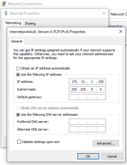
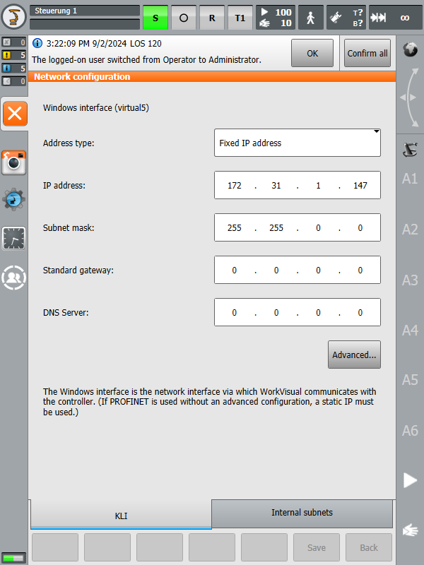
The IP address of the KLI interface of the robot can be configured on the robot’s smartPAD under: Main Menu/Start-up/Network configuration. The default address is 172.31.1.147 but it can be changed to any other IPv4 address (see: Fig. 15).
Start WorkVisual on your computer.
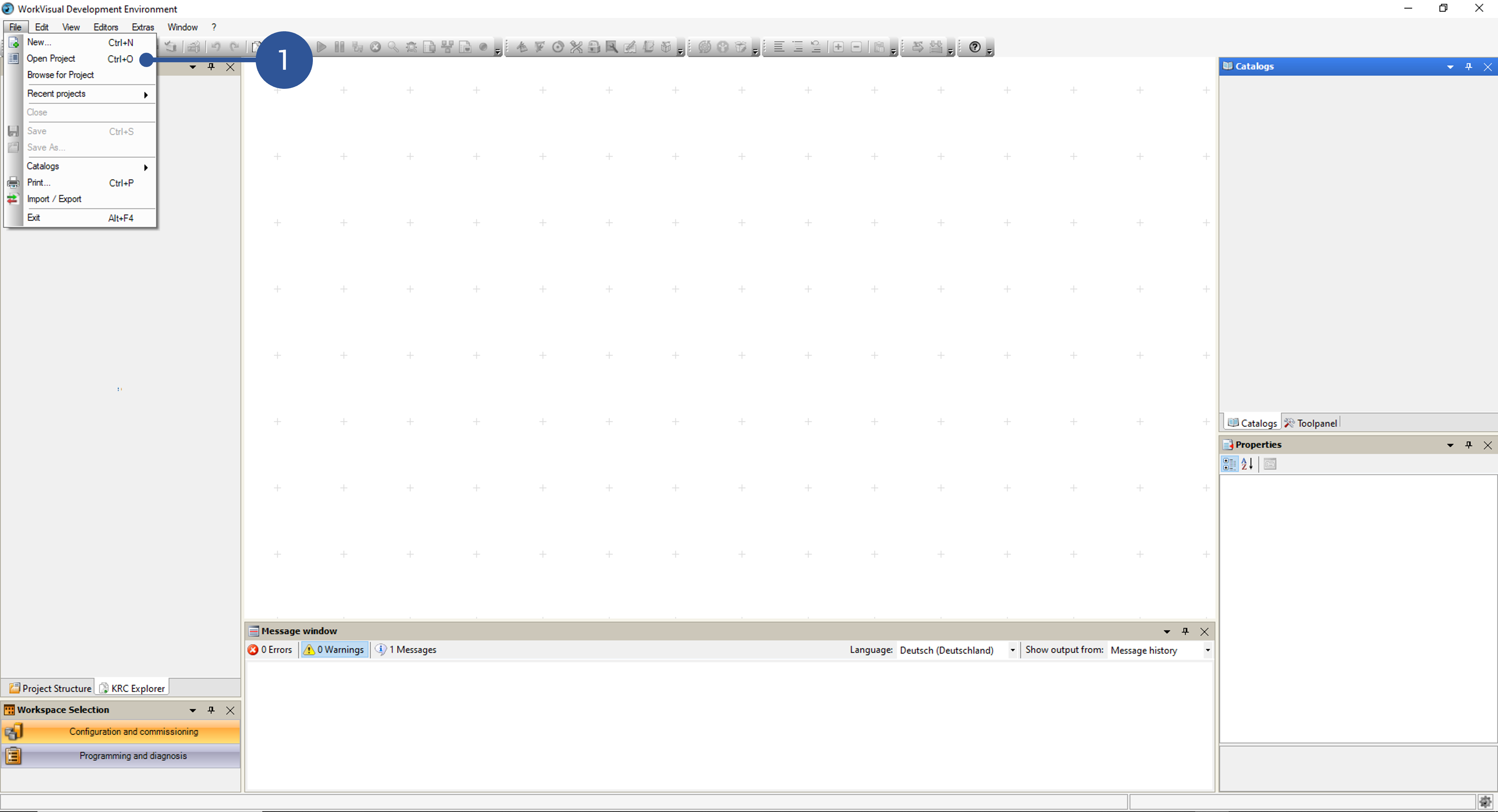
After the software starts, click on Open Project from the file menu (Fig. 16/➊).
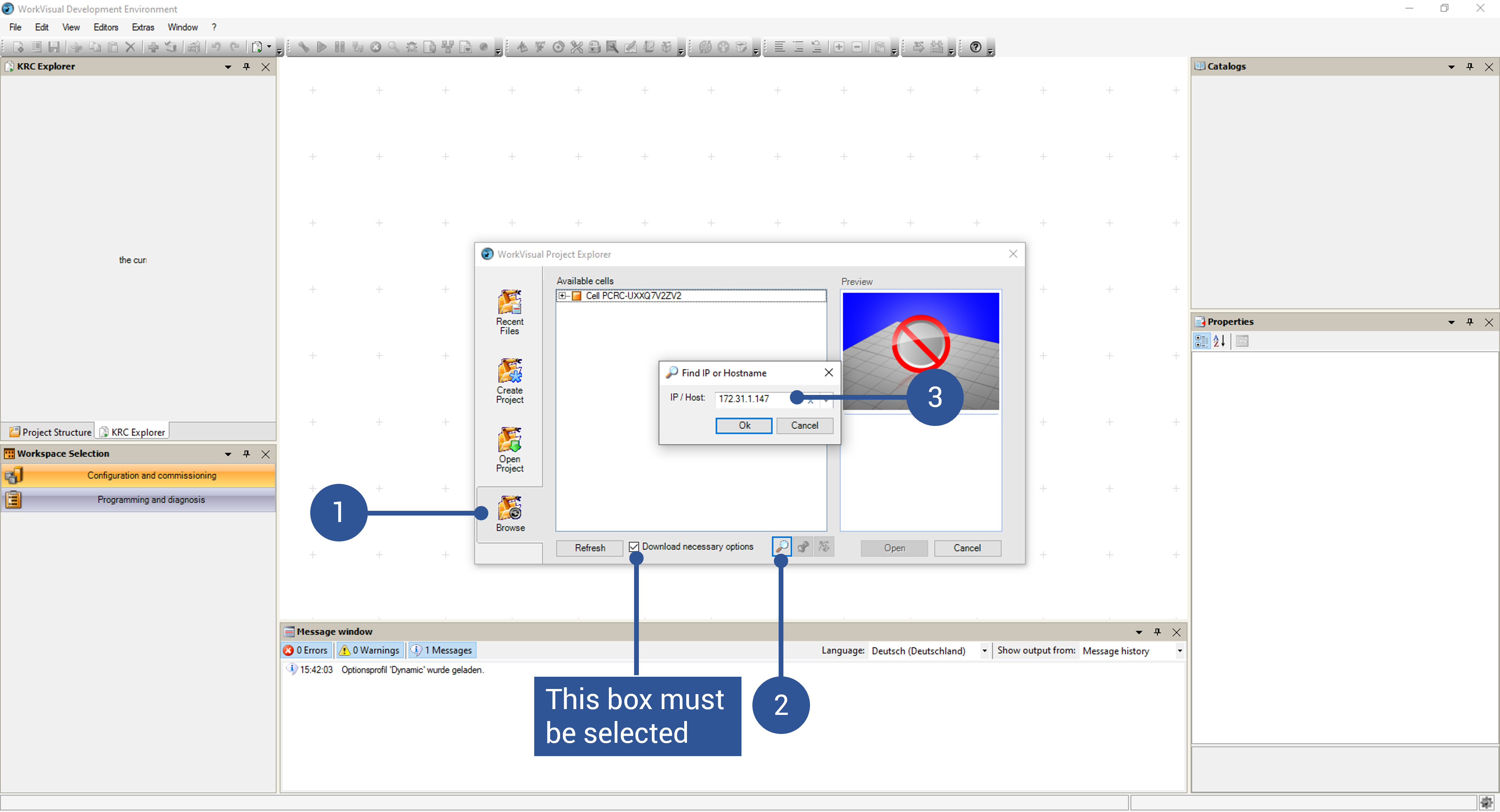
On the new window, click on Search (Fig. 17/➊). The robot should be found automatically. If not, search for the robot IP manually as illustrated in Fig. 17/➋ and ➌.
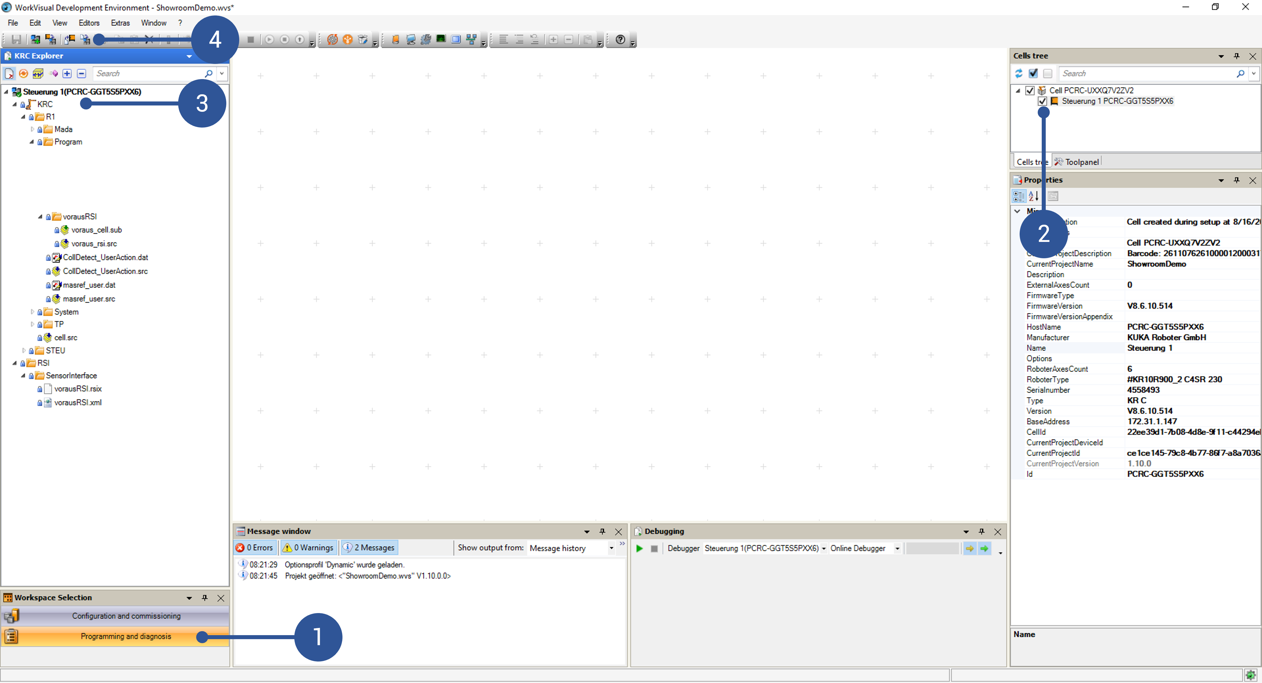
The files on the robot control can now be displayed by clicking on Programming and diagnosis (Fig. 18/➊). If necessary, the robot control can be selected using the corresponding checkbox (Fig. 18/➋). The main directory is shown in Fig. 18/➌. It might be necessary to click Load files and folders from controller in the toolbar at the top to synchronize your WorkVisual workspace with the one of your controller (Fig. 18/➍).
Note
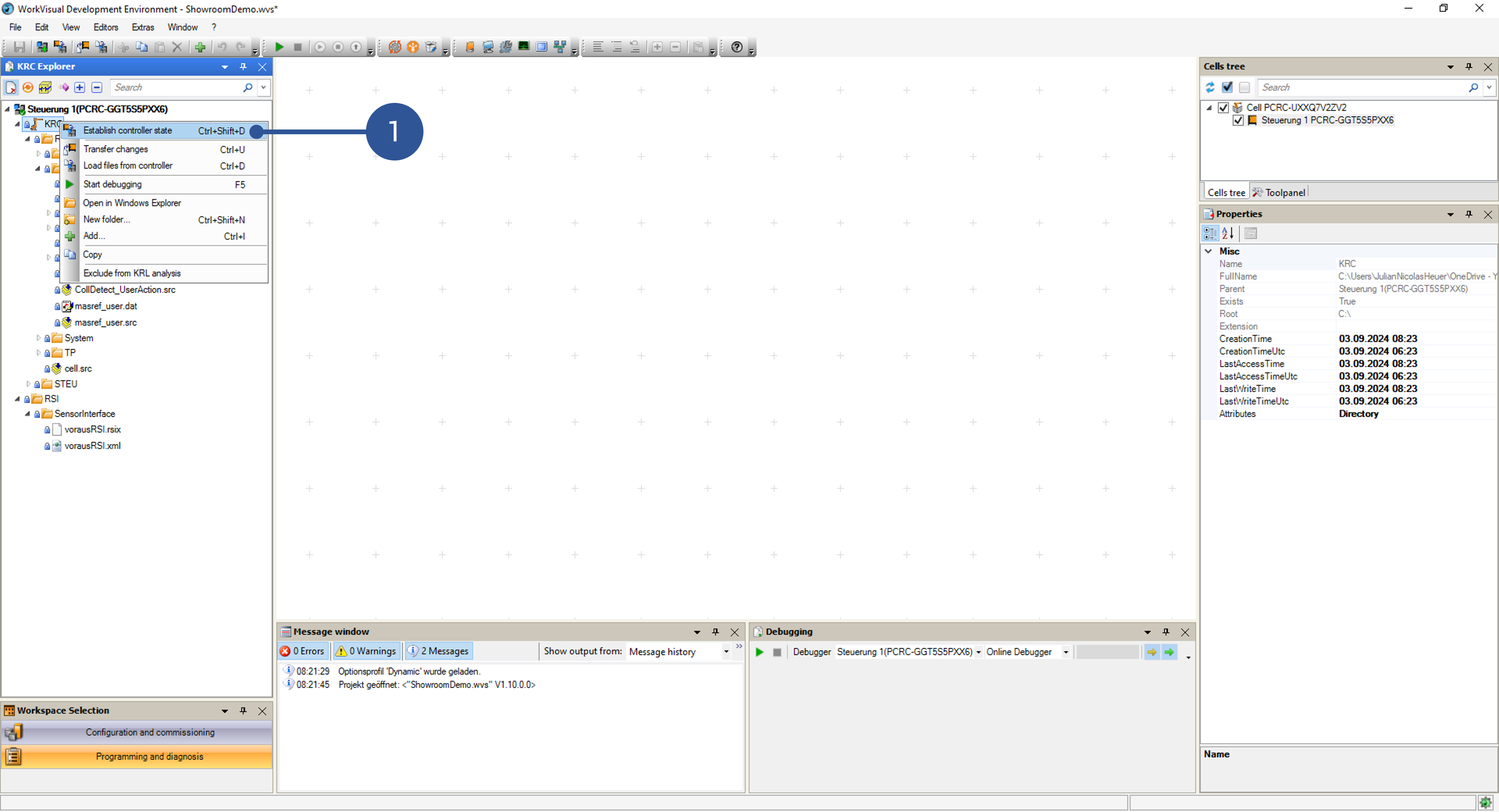
If the buttons are greyed out, you might need to click on Establish controller state (Fig. 19/➊) first.
Setting up the RSI interface
Before the voraus.operator can be used for controlling the KUKA robot, some additional network configurations have to be done, and certain files have to be uploaded to the KUKA control.
Required KUKA option packages:
KUKA.RobotSensorInterface 4.1 or compatible
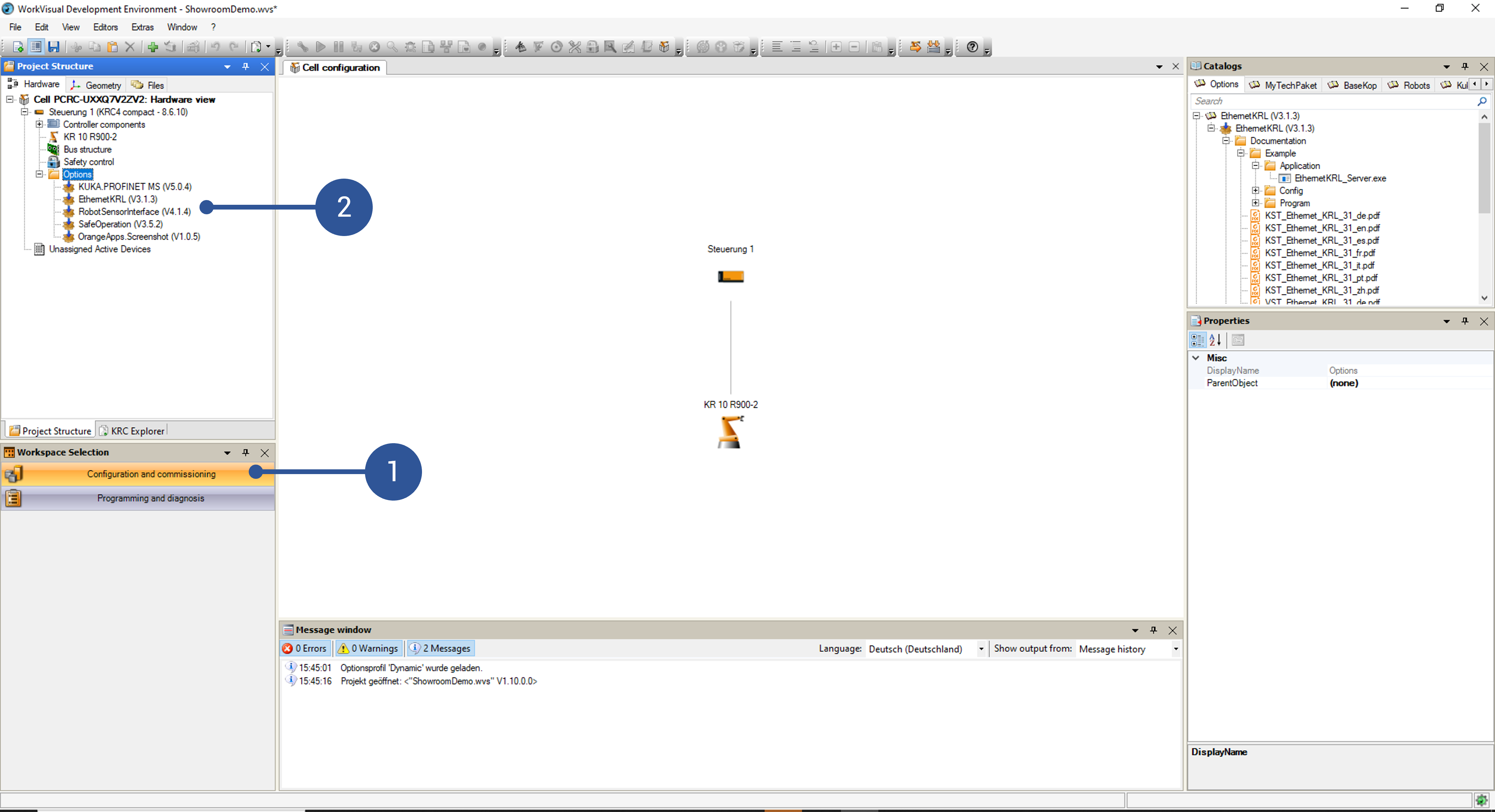
You can check the installed KUKA option packages via WorkVisual by switching to the Configuration and commissioning tab in the bottom left corner (Fig. 20/➊). Afterwards open the file explorer and then the Options folder of your control (Fig. 20/➋).
For the required voraus files, please refer to Robot Requirements, where all necessary files are listed.
Follow the next steps to set up the RSI interface between the robot and the voraus.core:
Using the robot’s smartPAD, create a new virtual network interface in the robot’s advanced network settings (e.g., virtual6, see Fig. 21). This interface requires a different IP address than the KLI interface shown in Fig. 15. but uses the same physical network port of the KRC. If a second virtual network had already been created, it can be used for the voraus.operator as well. In the interface settings the receiving task must be set to UDP. The virtual network interface must have the same network range as the IP address configured in configuration of the runtime (referred to as <IP_of_the_voraus.ipc>).
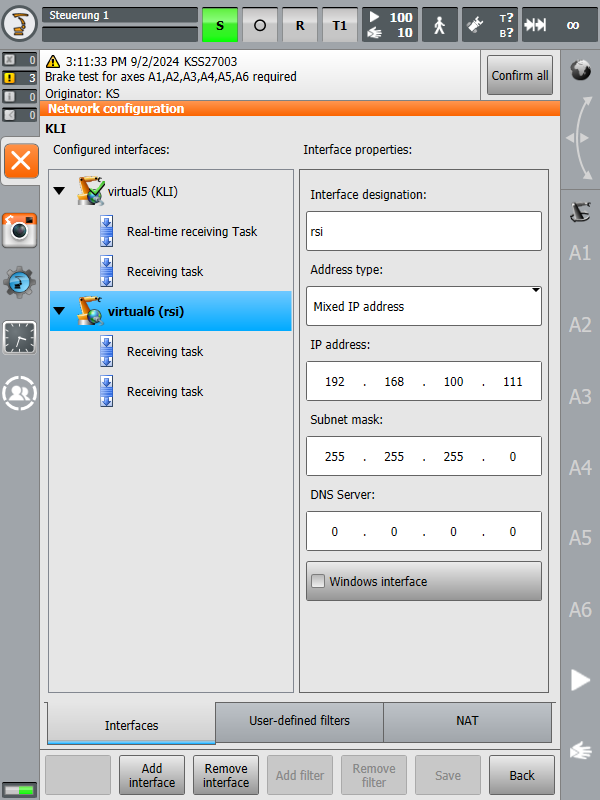
Fig. 21 RSI IP address on KUKA control
Import the RSI context file
vorausRSI.rsixvia WorkVisual. For that, switch to the Programming and diagnosis tab in the bottom left corner (Fig. 22/➊). From there, you can create new folders by right-clicking on an existing folder and selecting the New folder option (Fig. 22/➋) and add files directly via drag & drop. Alternatively, you can open the workspace in the default Windows Explorer by right-clicking on a folder and selecting Open in Windows Explorer (Fig. 22/➌).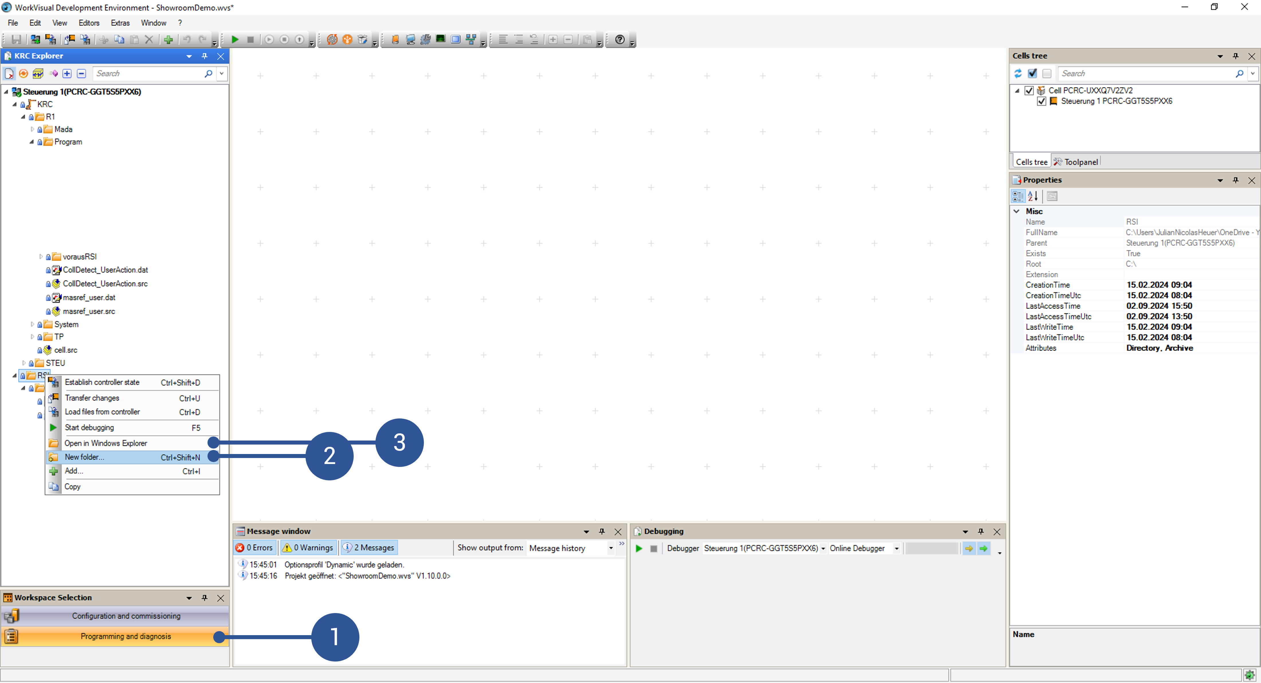
The
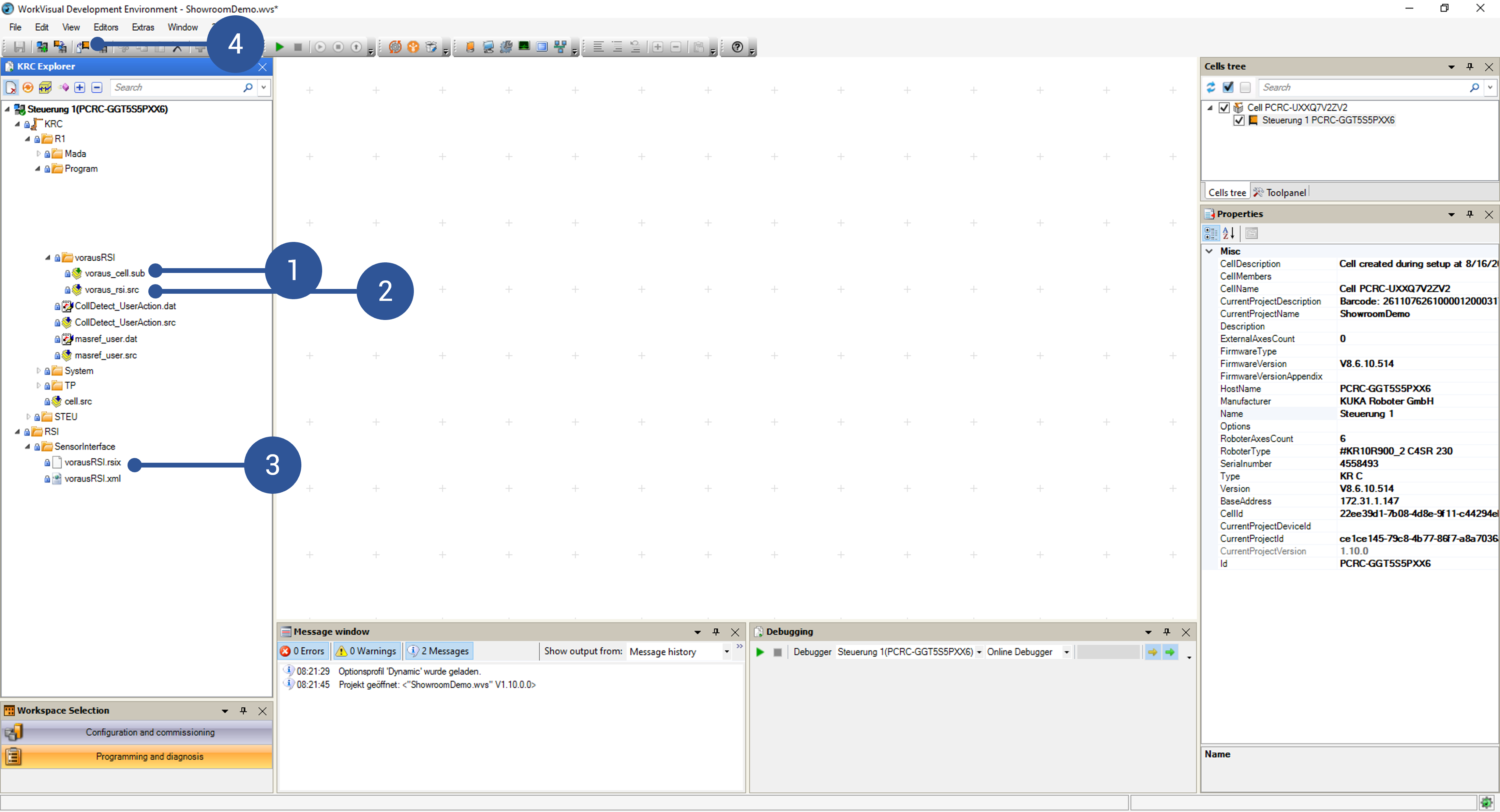
vorausRSI.rsixcontext file should be moved to RSI/” -> “SensorInterface/” (Fig. 23/➌).Using WorkVisual, copy the
vorausRSI.xmlfile to the same directory as the RSI context file. If needed, modify the IP address of the voraus.ipc:<ROOT> <CONFIG> <IP_NUMBER>IP_of_the_voraus.ipc</IP_NUMBER> <PORT>59152</PORT> <SENTYPE>ImFree</SENTYPE> <ONLYSEND>FALSE</ONLYSEND> </CONFIG>Add the following line into the section
Userdefined VariablesofSystem/$config.datINT VORAUS_TOOL_ID = 16Copy the file
voraus_cell.subto the program directory of the robot, e.g., to “KRC” -> “R1/” -> “Program/” -> “vorausRSI/” (Fig. 23/➊).Copy the file
voraus_rsi.srcto the program directory of the robot, e.g., to “KRC” -> “R1/” -> “Program/” -> “vorausRSI/” (Fig. 23/➋).Afterwards, the files have to be uploaded to the robot. You have to be logged in at least as an “expert” on the KUKA smartPAD for this. Click on Transfer changes to the controller as shown in Fig. 23/➍. Confirm the operation in the pop-up. When asked for remote access on the KUKA smartPAD, confirm it as well. When the pop-up disappears in WorkVisual, the process is complete.
On the smartPAD, configure the
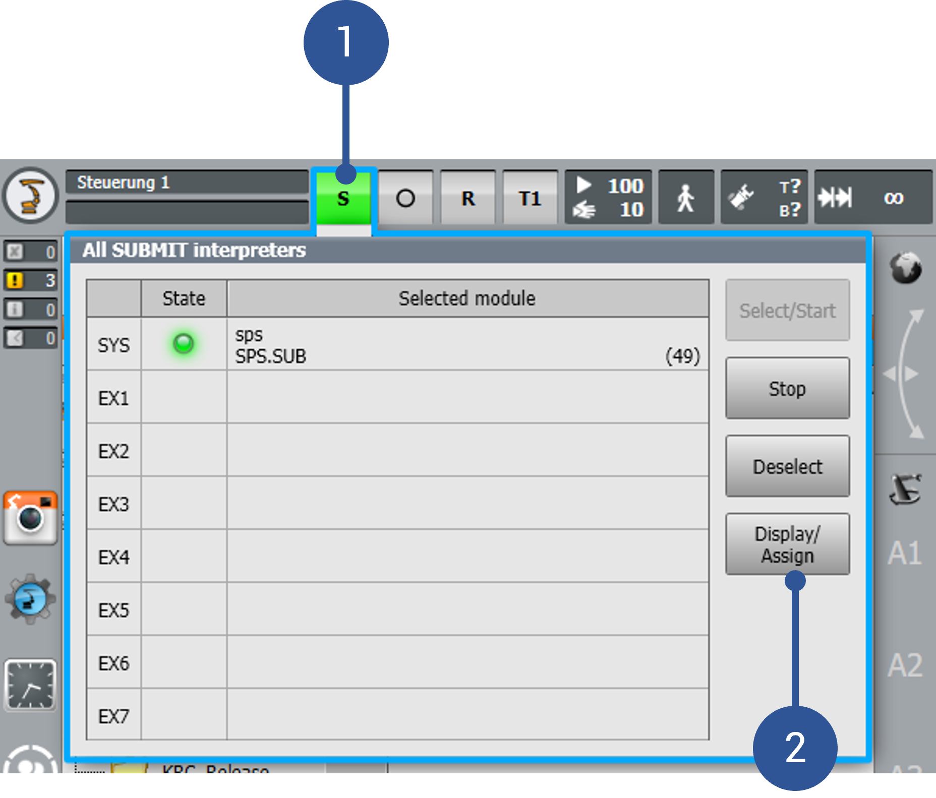
voraus_cell.subin the submit interpreter. This is only possible when logged in at least as an “expert”.Enter the Submit interpreter menu on the KUKA smartPAD (Fig. 24/➊).
Click on Display/Assign (Fig. 24/➋).
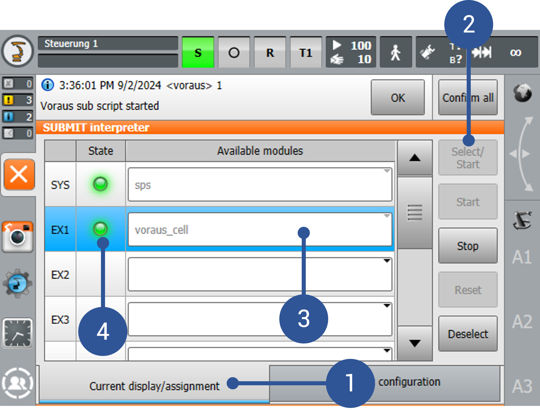
Enter Current Display/Assign (Fig. 25/➊)
Select the
voraus_cellscript in EX1 (Fig. 25/➌).Click on Select/Start (Fig. 25/➋).
Check if
voraus_cellis running (Fig. 25/➍)
Enter the Cold start-configuration section (Fig. 26/➊) and select
voraus_cellat EX1 (Fig. 26/➋).Leave the screen (Fig. 26/➌)
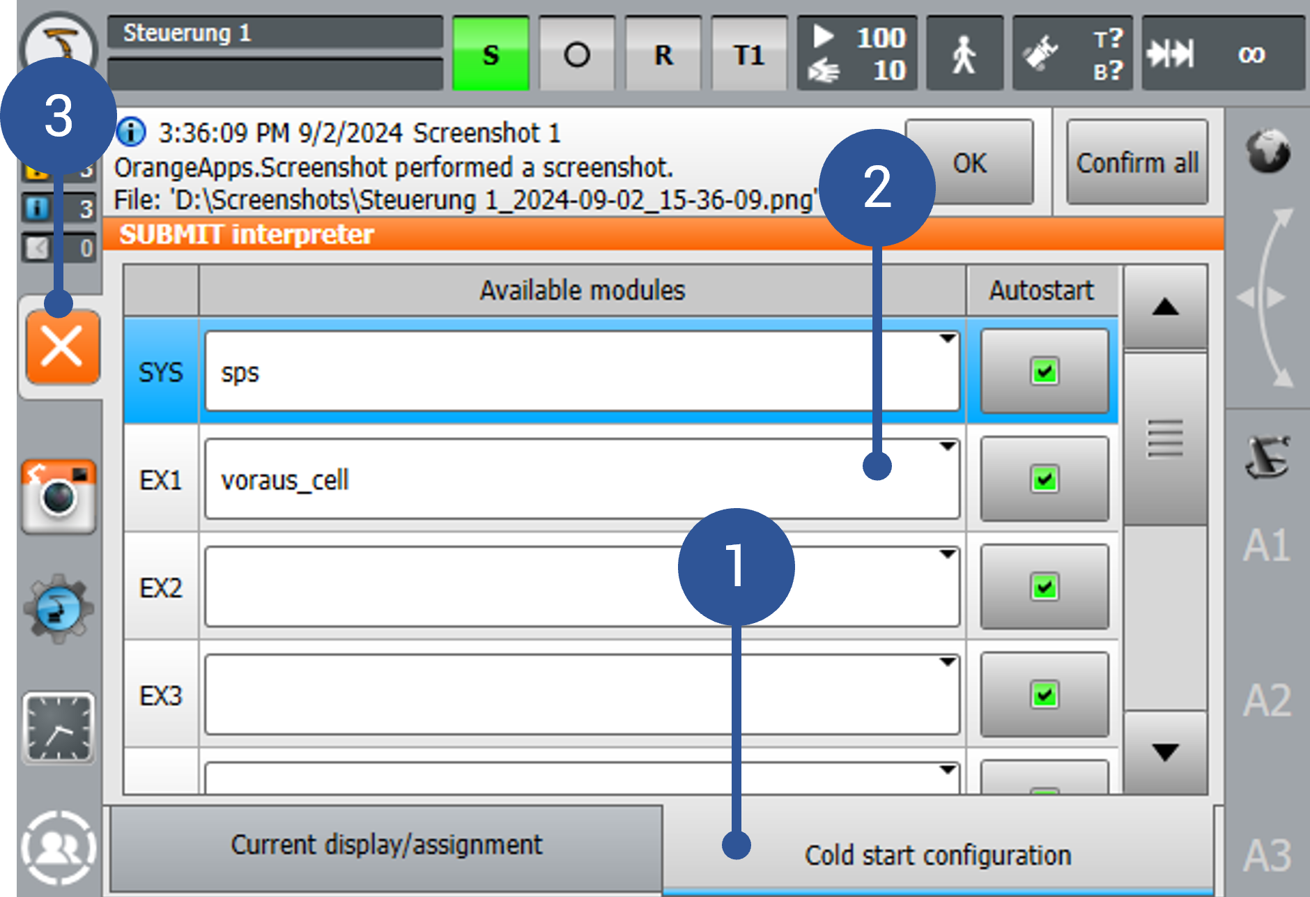
After this procedure the KUKA robot is ready to communicate with the voraus.core.
Installation for the voraus.core with Yaskawa robots
The following chapter describes the installation of the voraus.core with Yaskawa robots.
Setting up the Yaskawa robot for usage with the voraus.core
Warning
When using, operating and interacting with a Yaskawa robot, always obey to the instructions of the original Yaskawa manual.
The following sections assume that the Yaskawa robot is set up and can be moved with the teach pendant and the default Yaskawa cabinet software. If the robot is not set up yet, please follow the official Yaskawa documentation.
MotoPlus App Installation
As stated before, see Robot Requirements, the voraus.core requires a MotoPlus app to be installed on the Yaskawa
controller. The app is provided as a binary file (voraus-motoplus-app.out), please contact the
voraus support. The following steps describe the installation process:
Copy the provided app
voraus-motoplus-app.outto a USB drive.Insert the USB drive into the teach pendant.
Boot the controller in Maintenance mode (hold Main Menu during power-on).
Set the security level to MANAGEMENT.
Open the MotoPlus App menu and load the
.outfile from the USB drive.Reboot the controller.
After the reboot, voraus-motoplus-app should run in the background.
Motion Streaming Job
Motion Streaming requires a job on the Yaskawa teach pendant. If it does not already exist, please follow the steps below to create a new job:
Switch the teach pendant to TEACH mode (turn the key to the rightmost position).
Enter Management Mode (System Info -> Security).
Open JOB and click on CREATE NEW JOB.
Set the job name to VORAUS-MOTOPLUS-JOB, keep the other defaults, and press Execute.
Add the following instructions to the job:
0000 NOP
0001 SET B000 1
0002 WAIT IN#(1)=ON //"TEACH"_button
0003 END
Please create the instructions as follows:
Place the cursor on 0000, press INFORM LIST. Go to ARITH, and select SET. Press ENTER to create instruction 0001.
While still in INFORM LIST, go to IN/OUT and select WAIT. Press ENTER to create instruction 0002.
Emergency Stop Monitoring
While operating, the app continuously monitors the controller’s emergency stop signals. Two I/O signals are monitored every cycle:
External emergency stop - I/O address
80025Teach pendant emergency stop - I/O address
80026
Warning
Before using the app, ensure the right I/O addresses are set for the respective emergency stop signals.