
2.5. Prerequisites and voraus Conventions
This chapter describes the coordinate system conventions used throughout the voraus.core software stack. For a more detailed description of the coordinate systems, see the voraus Robot Control documentation.
2.5.1. Cartesian Pose Representation
A Cartesian pose in the voraus.core is always represented as a six-element vector:
[x, y, z, A, B, C]
where:
x,y,z: translational components in meters [m]A,B,C: rotational components in radians [rad]
The orientation is described using Cardan angles (also known as Tait–Bryan angles) following the intrinsic rotation
convention Rx * Ry' * Rz'':
A: rotation around the X-axis (first rotation)B: rotation around the Y-axis (second rotation, around the rotated Y’)C: rotation around the Z-axis (third rotation, around the twice-rotated Z’’)
Note
In the Python API (voraus Robot Arm), the Cardan angles are referred
to as rx, ry, rz instead of A, B, C. The meaning and convention are
identical.
Warning
Conversion of Cardan angles to other orientation representations (rotation matrices or quaternions) is subject to
gimbal lock when B (rotation around Y) approaches ±90°. In this case, A and C are no longer
independently distinguishable. The voraus.core handles this internally.
Internally, the voraus.core uses quaternions [w, x, y, z] for orientation interpolation during
Cartesian motions. The quaternion representation avoids gimbal lock and ensures smooth rotation paths. Conversion
between Cardan angles and quaternions is handled automatically.
2.5.2. Robot Coordinate System
Details about the robot coordinate system can be found in the voraus Robot Control documentation, in this section the main convention for the robot coordinate system (CS) used in the voraus.core software stack is summarized.
The Robot CS is the default coordinate system for specifying Cartesian poses and is usually fixed at the robot’s mounting point, i.e., the interface between the robot base and the surface it is mounted on. Some robot manufacturers define their internal origin at a different location than the mounting point. For example, FANUC places its internal coordinate origin at axis 2, as shown in Fig. 79. Yaskawa robots use the same axis 2 convention. The voraus.core handles the transformation between the manufacturer’s origin and the mounting point automatically.
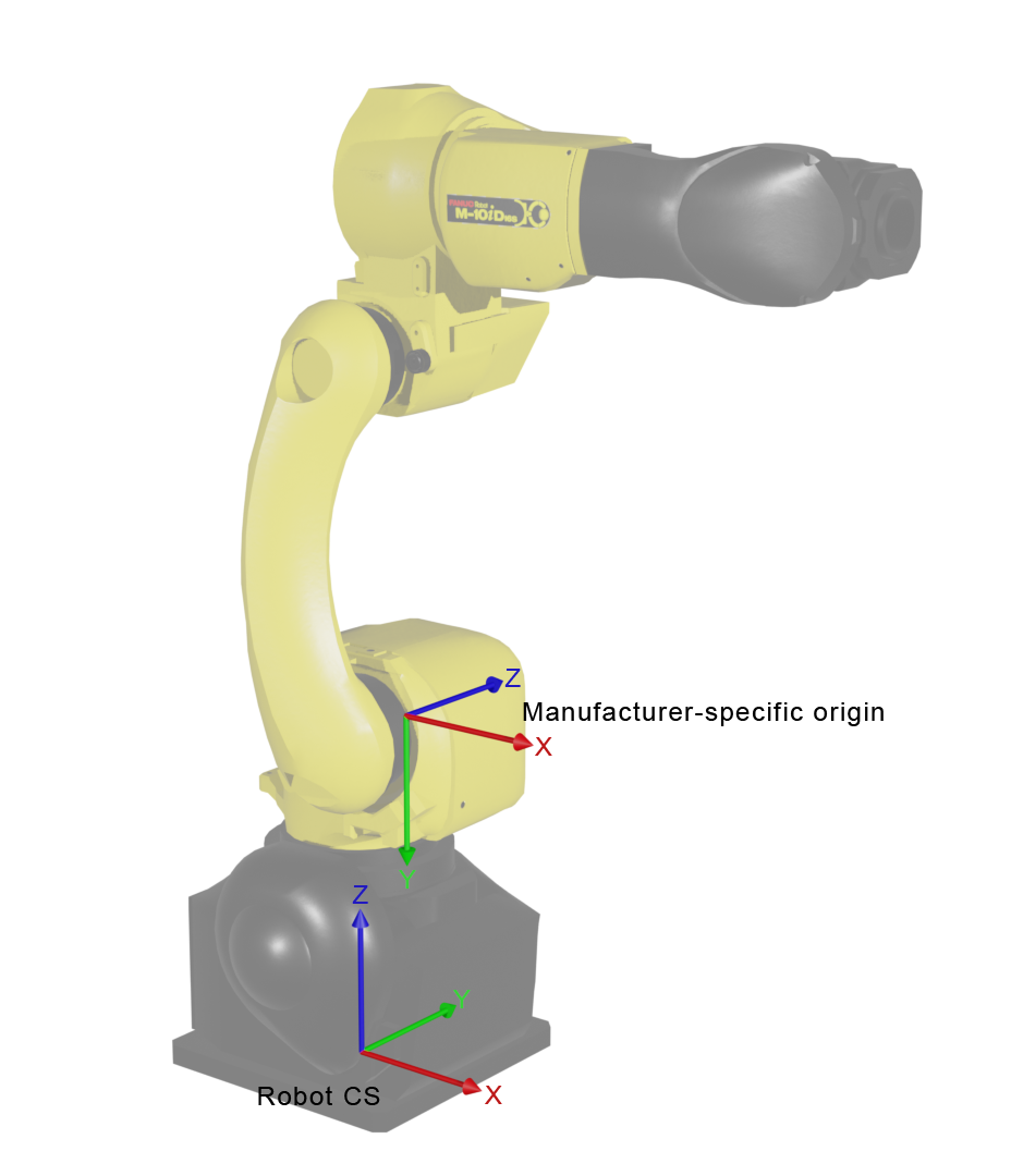
Fig. 79 Exemplary FANUC robot: Robot CS is located at the robot’s mounting point, the manufacturers internal origin is located at axis 2 (A2).
For KUKA robots the internal origin is located at the robot’s mounting point, which is also the Robot CS. This means that for KUKA robots, the Robot CS and the manufacturer’s internal origin coincide, as shown in Fig. 80.
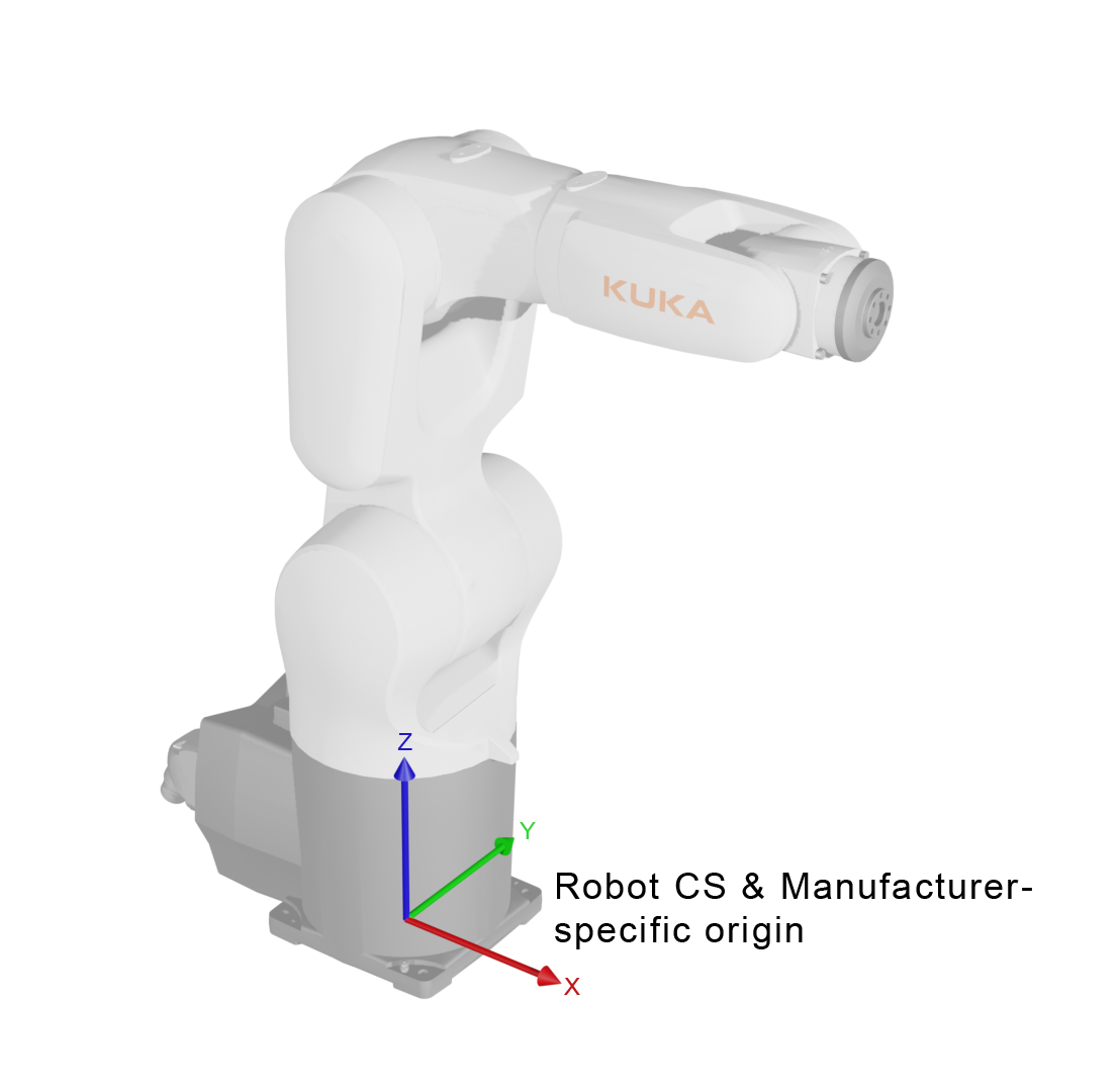
Fig. 80 Exemplary KUKA robot: Robot CS is located at the robot’s mounting point, the manufacturers internal origin is located at the same point.