
FANUC Robots
The following chapter describes the installation of the voraus.core with FANUC robots.
Warning
When using, operating and interacting with a FANUC robot, always obey the instructions of the original FANUC manual.
The following sections assume that the FANUC robot is set up and can be moved with the teach pendant and the default FANUC cabinet software. If the robot is not set up yet, please follow the official FANUC documentation.
In order to connect the voraus.core to a FANUC system, the FANUC cabinet has to be prepared first.
Checking Installed Software Options
Note
Supported FANUC Cabinets
The procedure described in this section applies to the R-30iB Plus and R-30iB Compact Plus cabinets, which are listed in Robot Requirements.
The voraus.core needs the activated FANUC software module R912 - Remote Motion Interface to communicate with the control cabinet. In order to check that it is activated, interact with the teach pendant:
Press: MENU → 0: NEXT → 4: STATUS → 2: Version ID.
Press: NEXT → ORDER FI (F3).
Options are listed, click YES for further displaying until you find R912 Remote Motion (Fig. 5).
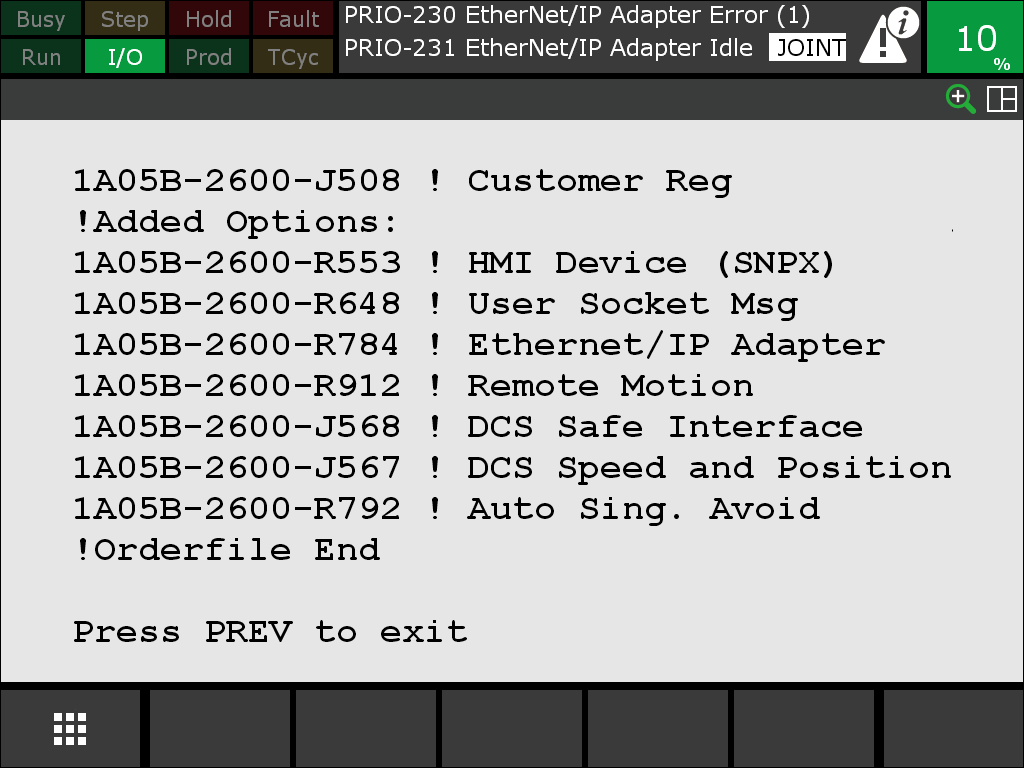
If you do not find R912 Remote Motion, the voraus.core cannot connect successfully. Please contact FANUC support to buy or install the required software options.
Connecting the Robot to the Network
Connect the FANUC control cabinet to the voraus.ipc as follows.
Warning
Please familiarize yourself with the safety instructions in the FANUC manual. Beware of electric shock. Shut down the robot and ground the control cabinet prior to opening it.
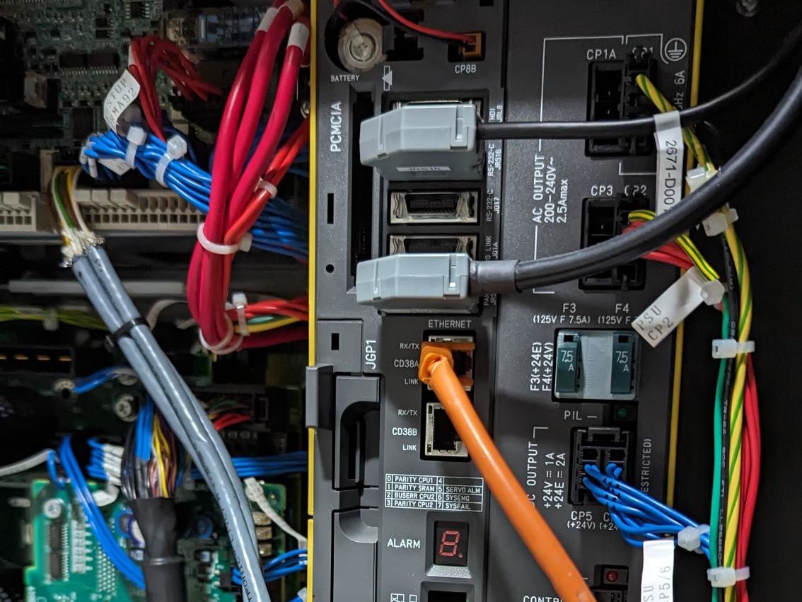
Open the control cabinet and connect the voraus.ipc via Ethernet with port 1 (CD38A) inside the cabinet. Port 1 is marked with the orange cable in Fig. 6.
The network connection has to be configured. Start the robot and navigate on the teach pendant to the network settings via:
MENU → 6: SETUP → 0: NEXT → 0: NEXT → 1: Host Comm → TCP/IP → ENTER.
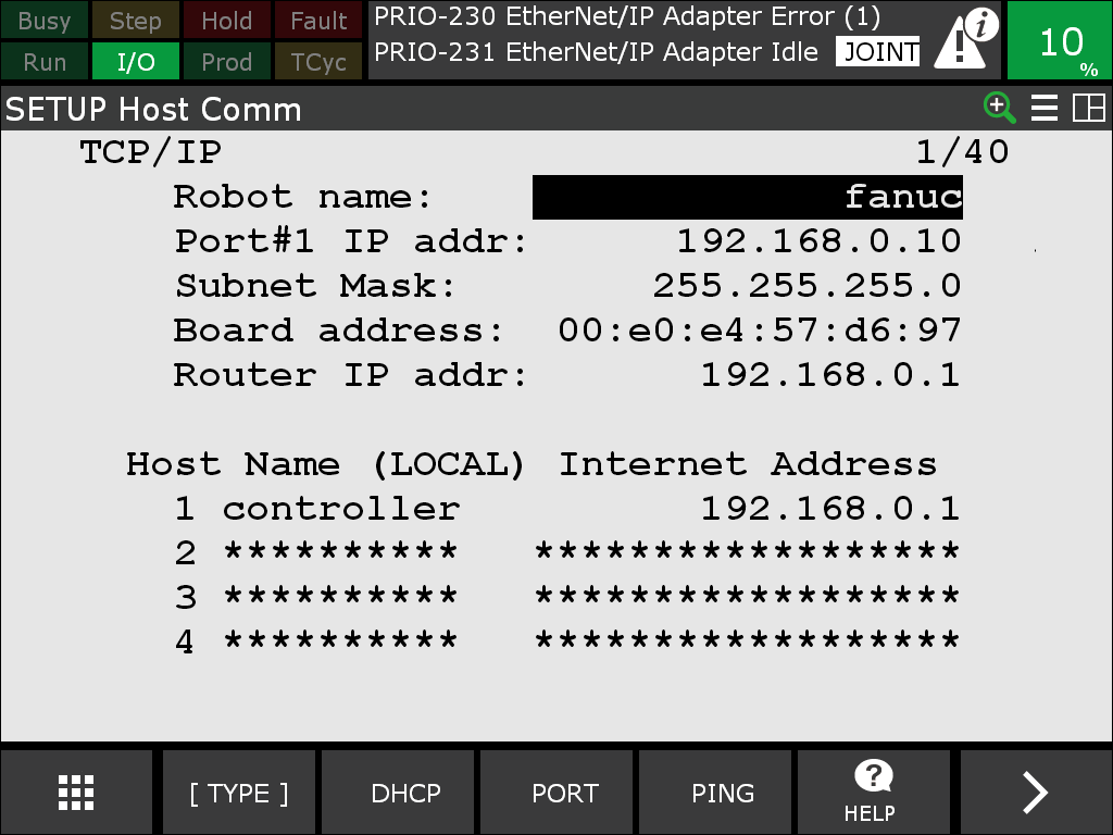
Then configure the settings for port 1 according to your network setup. In case you use the voraus.ipc, the router IP address has to be 192.168.0.1. For use with a different configuration, please contact voraus support. Fig. 7 shows an example configuration.
Switching to the Right Operating Mode
Warning
Mandatory Setting: Confirmation for AUTO
The setting Confirmation for AUTO must be set on the cabinet. Without this setting, the robot cannot be operated with the voraus.core.
Different types of FANUC controllers implement this setting differently. The description below is only one possible way to set it. Therefore, always also consult the FANUC manual that is shipped with the robot.
Since the voraus.core is an external control for the FANUC robot, it can only take control of the robot, if the cabinet is switched to the automatic mode. Hence, instructions can no longer be input via the teach pendant. Switch off the teach pendant by turning the operating mode switch shown in Fig. 8. If the teach pendant displays options to switch the operating mode, select AUTO and enter the PIN. The default PIN is 1111.
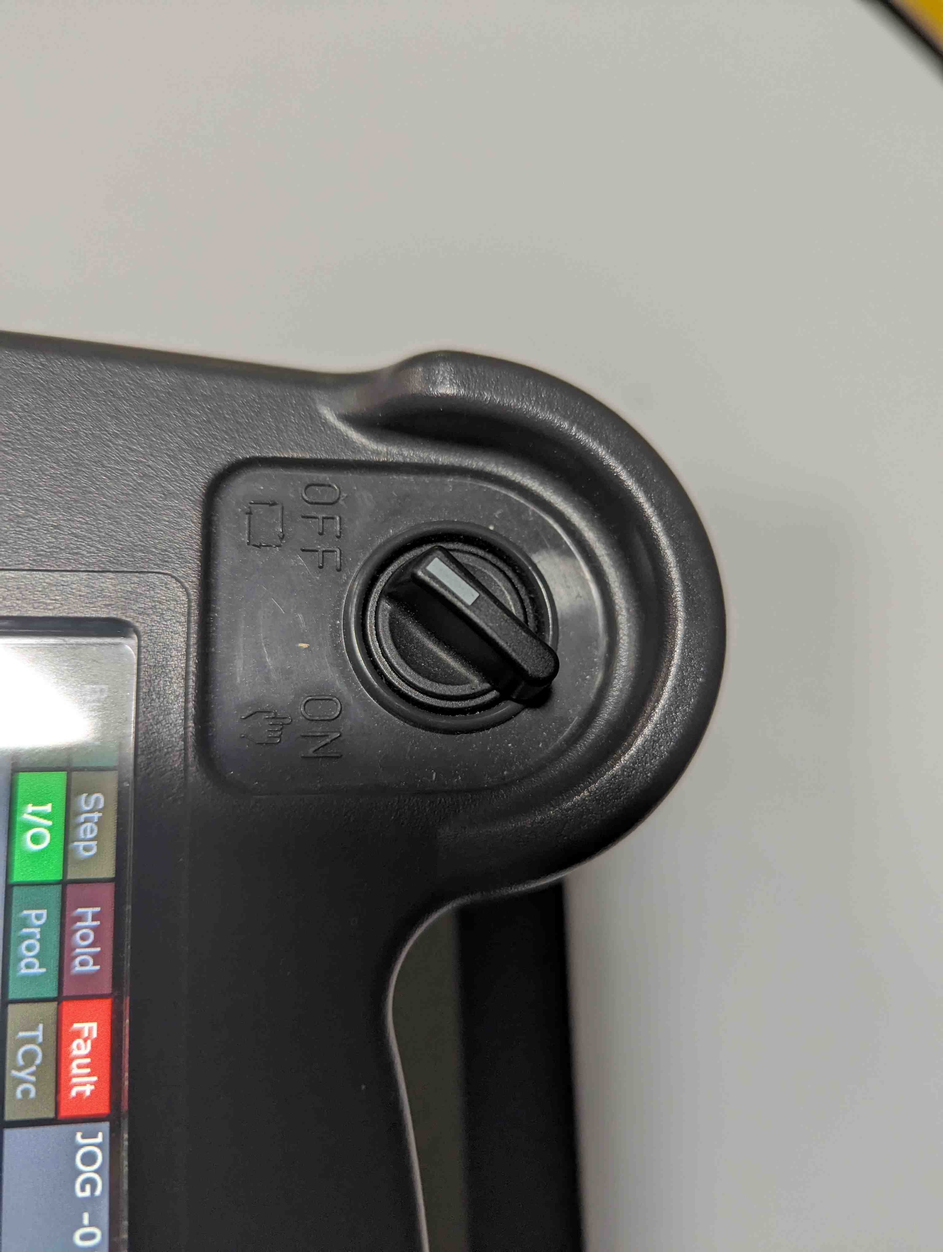
Fig. 8 Switch for toggling between manual and automatic mode
Some FANUC robots may have a key switch at the cabinet. If there was no option to choose the AUTO mode on the screen, turn the key switch at the cabinet to AUTO (Fig. 9).
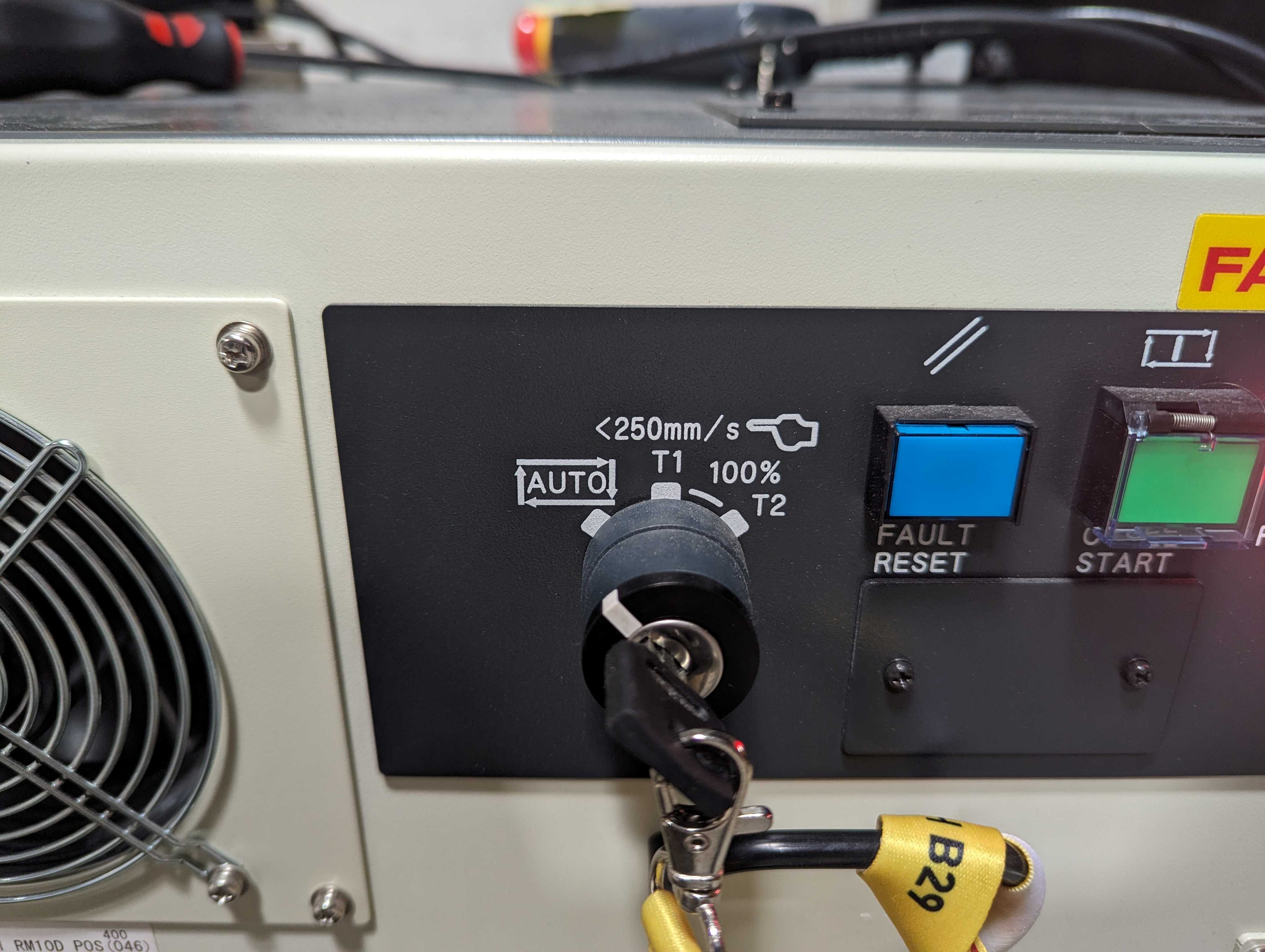
Fig. 9 Key switch for toggling between manual and automatic mode
Before starting the voraus.core, the FANUC robot should not display any errors. If the teach pendant displays errors, reset them by pressing RESET on the teach pendant. Make sure, the emergency stop is unlocked. The voraus.core cannot take control of the robot if the emergency stop on the teach pendant is pressed.
Configuring Automatic Mode to Conform to Manual Mode Limitations according to EN ISO 10218-1
EN ISO 10218-1 defines, that a limited move set with reduced speeds of 250 mm/s shall be used when jogging, teaching, programming, and verifying robot programs. The FANUC control cabinet implements an operation mode T1 which conforms to these requirements. However, as previously described, the voraus.core can only take control of the robot, if the cabinet is switched to the automatic mode AUTO.
In order to still conform to EN ISO 10218-1 when teaching robot programs with the voraus.core, the settings of the AUTO mode have to be manually configured to dynamically change the limitations to T1 behavior. The emulated T1 behavior is subsequently called ET1. An external input, e.g., a key switch, or a virtual setting on the controller can then be used to switch between true AUTO mode and ET1. In the following example, a virtual setting is used.
To set up ET1 mode, create two SIR (Safe Internal Relay) variables in the safety system.
Navigate on the teach pendant via MENU → 0: NEXT → 6: SYSTEM → 8: DCS → 1 Safe I/O Status:.
Then press ENTER and select F2 DATA → 5: SIR.
Name SIR1 Automatic Mode and SIR2 Movement Allowed as shown in Fig. 10.
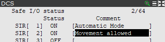
Which signals are used to change the variables is configured in the DCS menu 2 Safe I/O connect. Fig. 11 shows the settings to use. The status SIR[1] - Automatic Mode is changed manually in this example and no input is connected to the cabinet. If an input is used, map an SSI (Safe System Input) with the matching port your switch is connected to.
The status SIR[2] - Movement Allowed combines an enabling device with the current mode SIR[1] - Automatic Mode.
It is possible to use the enabling device of the FANUC teach pendant.
This input can be found at SSI[5].
If an external enabling device is used, map an SSI with the matching port your switch is connected to.

The variables SIR[1] - Automatic Mode and SIR[2] - Movement Allowed can now be used to activate and deactivate limitations. Two limitations are needed. On the teach pendant as before navigate to the DCS menu. Switch to menu entry “6 Cart. speed check” and select the configuration to modify with the [DETAIL] button.
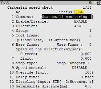
The first configuration shown in Fig. 12 relates to standstill monitoring
and defines a speed limit of zero.
This means, if the robot moves, an SS1 stop is performed immediately.
Take care to change the fields Disabling input to SIR[2] and Stop type to
Stop Category 1.
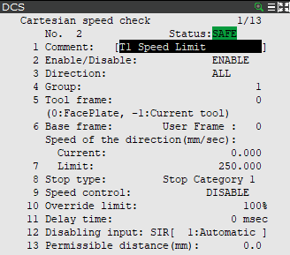
The second configuration shown in Fig. 13 defines a speed limit of 250 mm/s according
to the manual mode at reduced speed in EN ISO 10218-1.
If the robot movement exceeds this speed limit,
an SS1 stop is performed immediately.
Take care to change the fields Disabling input to SIR[1] and Stop type to
Stop Category 1 and Limit to 250.
Warning
Test the application of your settings before using the robot.
The setup of ET1 is now complete. Switch to ET1 when programming your application by setting SIR[1] - Automatic Mode to Off (2 Safe I/O connect → SIR[1] → Input1 → OFF). If you want to leave ET1 and switch back to the true AUTO mode, switch SIR[1] - Automatic Mode to On.
Next Steps
The installation of the voraus.core is now complete. Continue with the configuration of the software stack for your setup as described in Configuration for the voraus.core.
After the configuration, the voraus.core can be started and activated as described in Starting, Stopping, and Activating the voraus.core.