
KUKA Robots
The following chapter describes the installation of the voraus.core with KUKA robots.
Note
Supported KUKA Cabinets
The installation described in this chapter applies to the KR C4, KR C4 compact, KR C5, and KR C5 micro cabinets. The installation description for the KR C5-2 and KR C5 micro-2 cabinets is still in progress. Until it is available, please contact voraus support.
Warning
When using, operating and interacting with a KUKA robot, always obey the instructions of the original KUKA manual.
The following sections assume that the KUKA robot is set up and can be moved with the KUKA smartPAD and the default KUKA controller software. If the robot is not set up yet, please follow the official KUKA documentation. Also, it is assumed that the user knows the basic steps on how to operate the robot with the KUKA smartPAD like switching the operating mode and starting/stopping KUKA programs.
In order to connect the voraus.core to a KUKA system, the KUKA controller has to be prepared first. For this, follow the chapters WorkVisual installation and Setting up the RSI interface.
WorkVisual Installation
In order to work with files on the KUKA robot controller, the KUKA software WorkVisual is recommended. A quick installation guide can be found in this section.
Get the software installation file, e.g., from https://my.kuka.com (Version 6.0 or compatible required).
Extract and install the software using the default settings.
Either directly connect an Ethernet cable from the Ethernet port of the robot controller to your computer or use an Ethernet switch in between the two components.
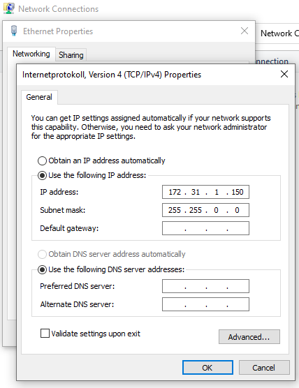
Configure the connected Ethernet port of your computer to be in the same network as the KLI interface of the KUKA robot (see exemplary IP address in Fig. 14).
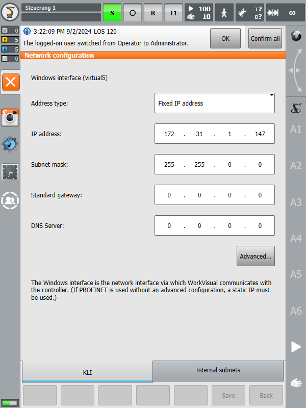
The IP address of the KLI interface of the robot can be configured on the robot’s smartPAD under: Main Menu/Start-up/Network configuration. The default address is 172.31.1.147 but it can be changed to any other IPv4 address (see: Fig. 15).
Start WorkVisual on your computer.
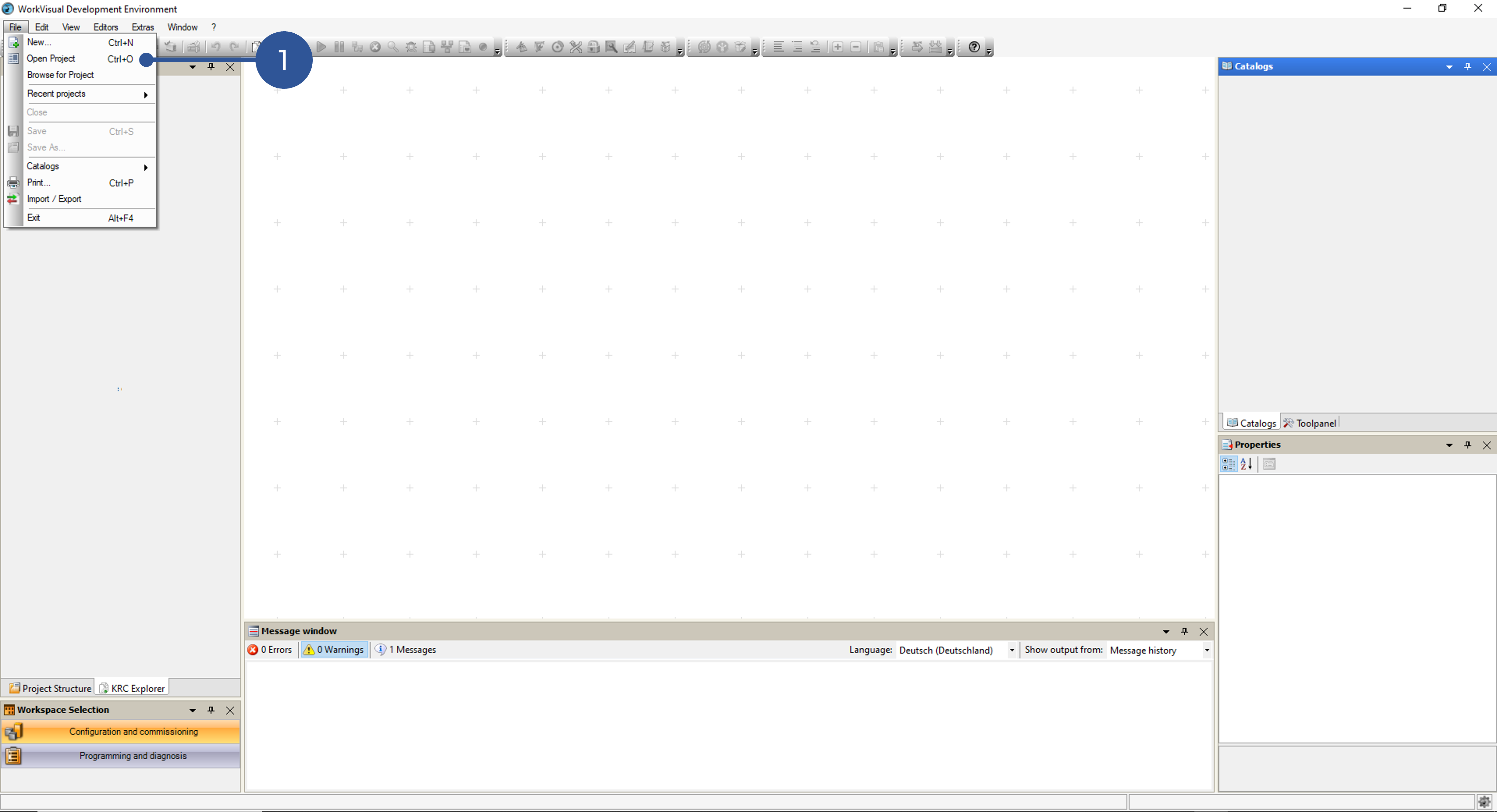
After the software starts, click Open Project from the file menu (Fig. 16/➊).
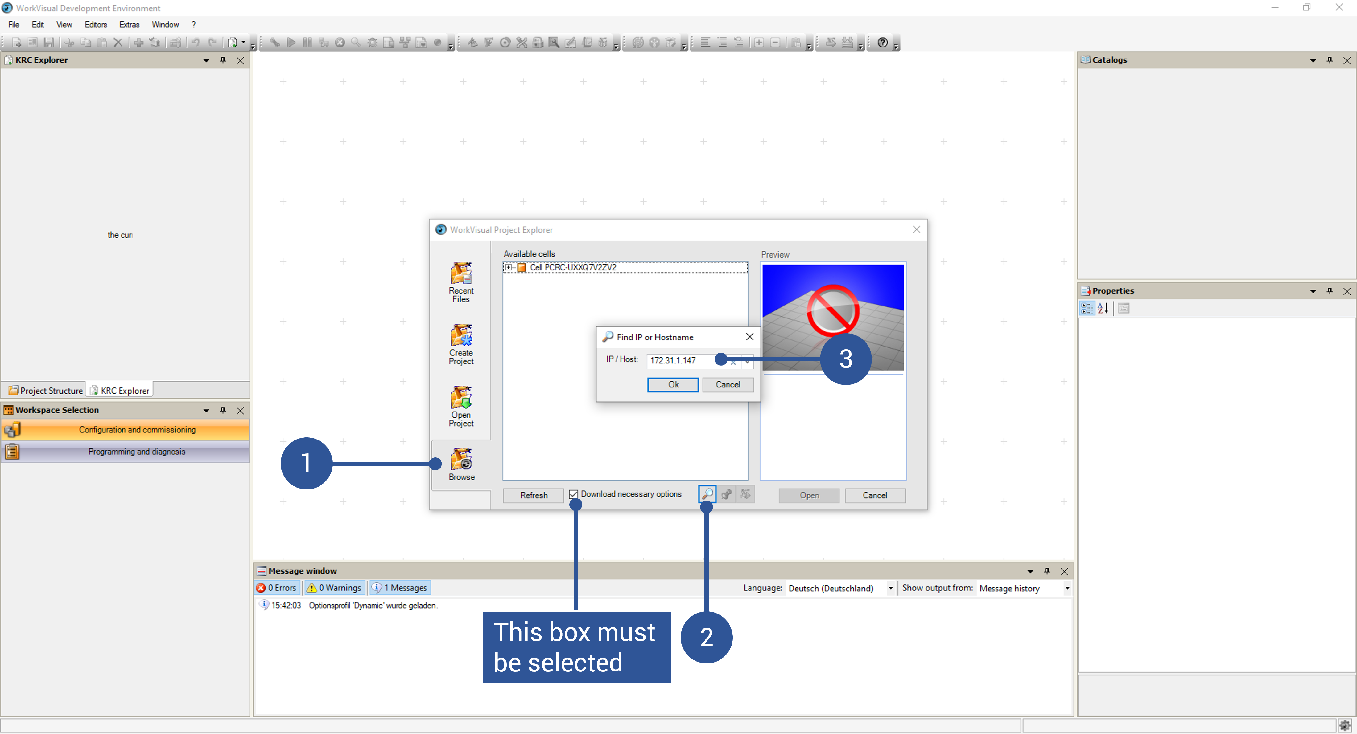
On the new window, click Search (Fig. 17/➊). The robot should be found automatically. If not, search for the robot IP manually as illustrated in Fig. 17/➋ and ➌.
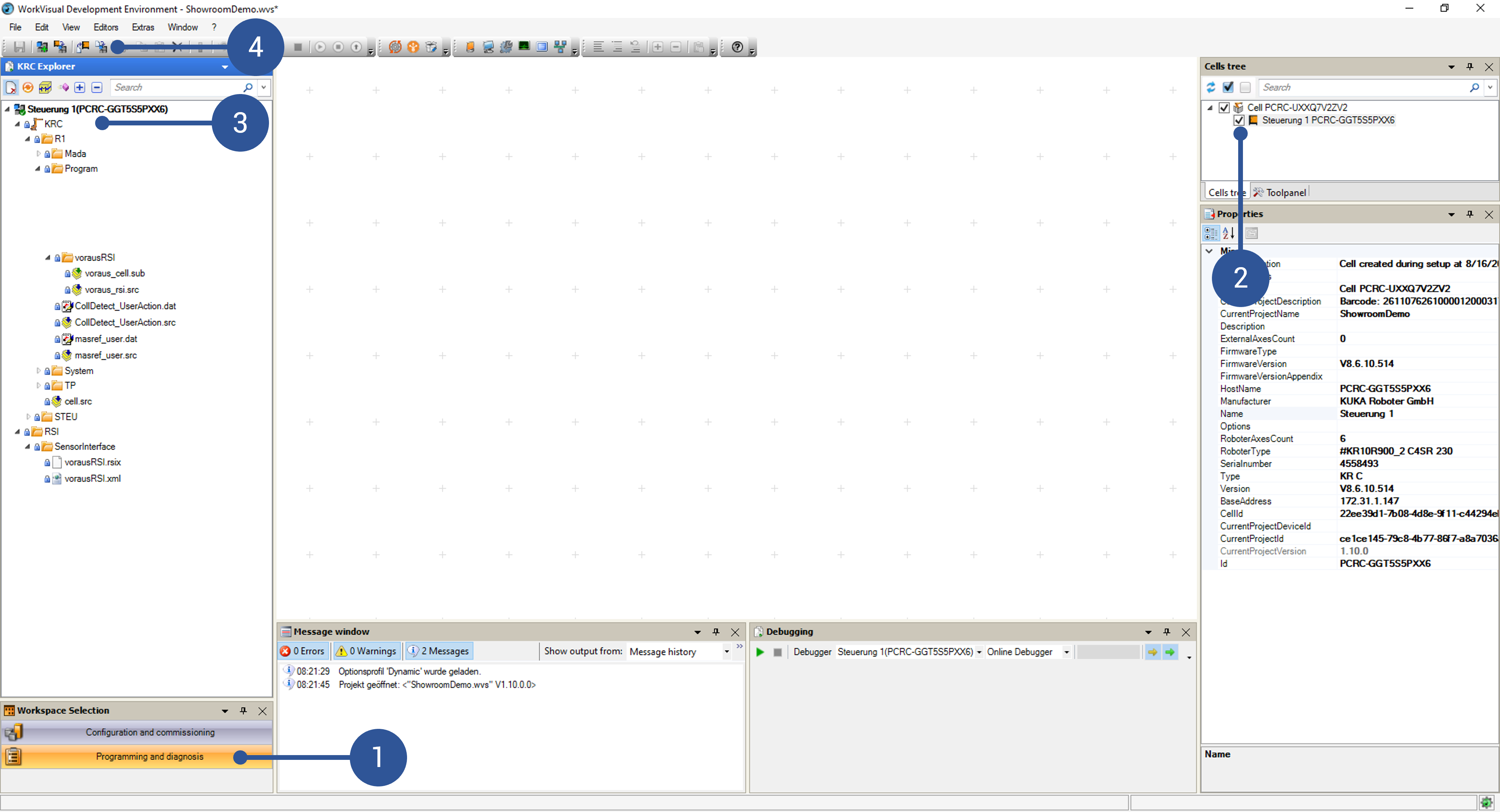
The files on the robot control can now be displayed by clicking Programming and diagnosis (Fig. 18/➊). If necessary, the robot control can be selected using the corresponding checkbox (Fig. 18/➋). The main directory is shown in Fig. 18/➌. It might be necessary to click Load files and folders from controller in the toolbar at the top to synchronize your WorkVisual workspace with the one of your controller (Fig. 18/➍).
Note
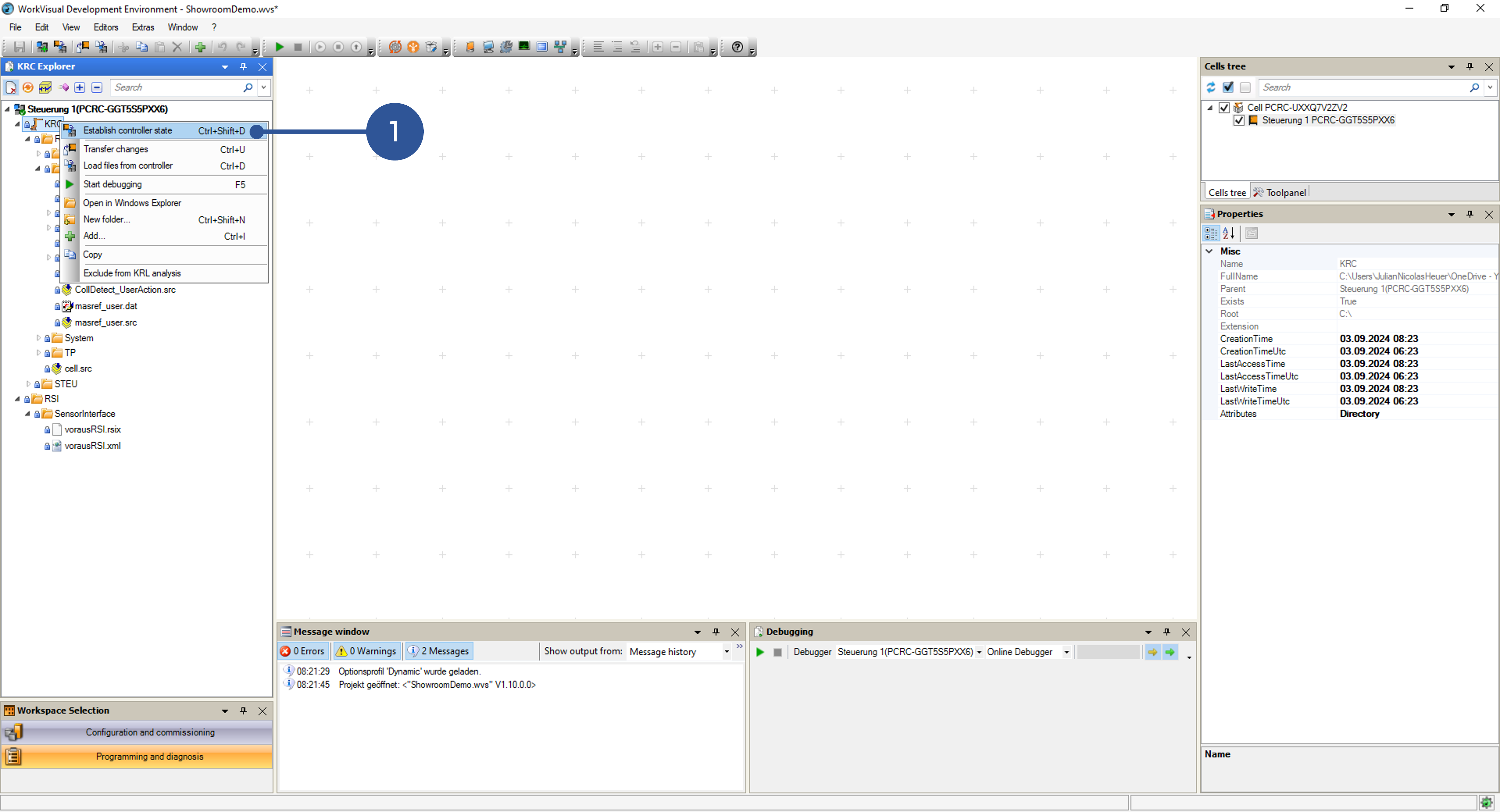
If the buttons are grayed out, you might need to click Establish controller state (Fig. 19/➊) first.
Setting up the RSI Interface
Before the voraus.operator can be used for controlling the KUKA robot, some additional network configurations have to be done, and certain files have to be uploaded to the KUKA control.
Required KUKA option packages:
KUKA.RobotSensorInterface 4.1 or compatible
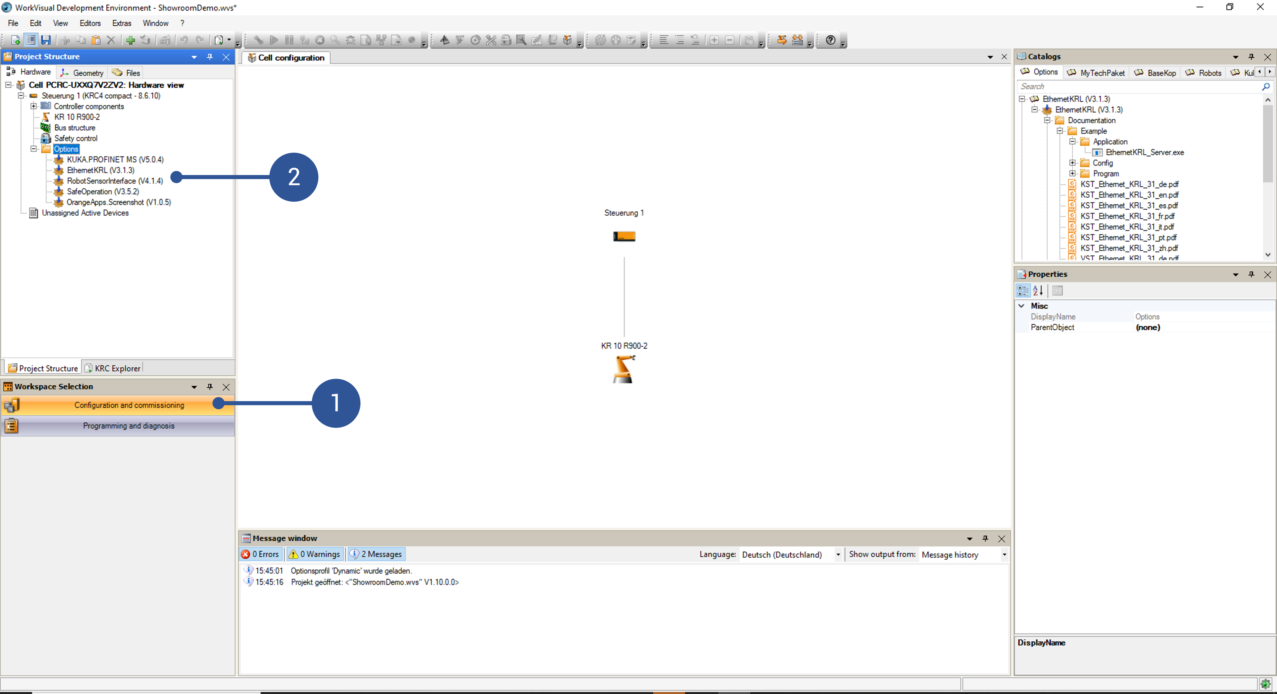
You can check the installed KUKA option packages via WorkVisual by switching to the Configuration and commissioning tab in the bottom left corner (Fig. 20/➊). Afterwards, open the file explorer and then the Options folder of your control (Fig. 20/➋).
For the required voraus files, please refer to Robot Requirements, where all necessary files are listed.
Follow the next steps to set up the RSI interface between the robot and the voraus.core:
Using the robot’s smartPAD, create a new virtual network interface in the robot’s advanced network settings (e.g., virtual6, see Fig. 21). This interface requires a different IP address than the KLI interface shown in Fig. 15, but uses the same physical network port of the KRC. If a second virtual network had already been created, it can be used for the voraus.operator as well. In the interface settings, the receiving task must be set to UDP. The virtual network interface must have the same network range as the IP address configured in configuration of the runtime (referred to as <IP_of_the_voraus.ipc>).
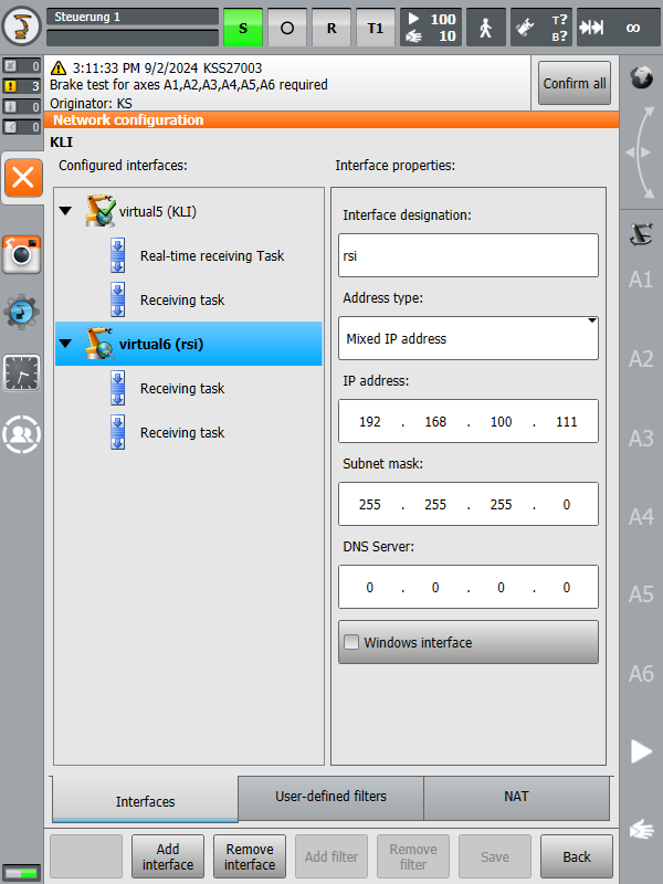
Fig. 21 RSI IP address on KUKA control
Import the RSI context file
vorausRSI.rsixvia WorkVisual. For that, switch to the Programming and diagnosis tab in the bottom left corner (Fig. 22/➊). From there, you can create new folders by right-clicking an existing folder and selecting the New folder option (Fig. 22/➋) and add files directly via drag & drop. Alternatively, you can open the workspace in the default Windows Explorer by right-clicking a folder and selecting Open in Windows Explorer (Fig. 22/➌).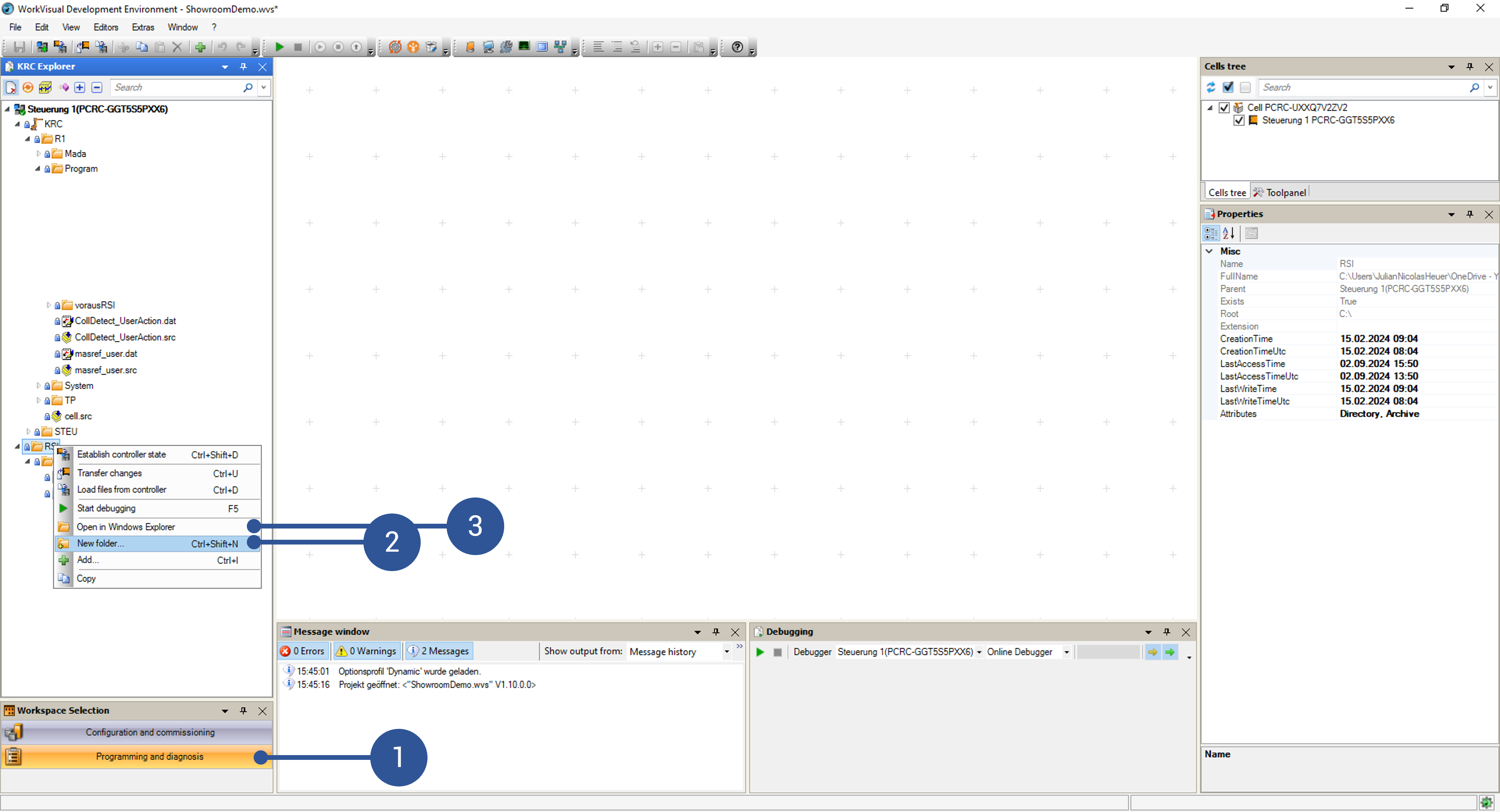
The
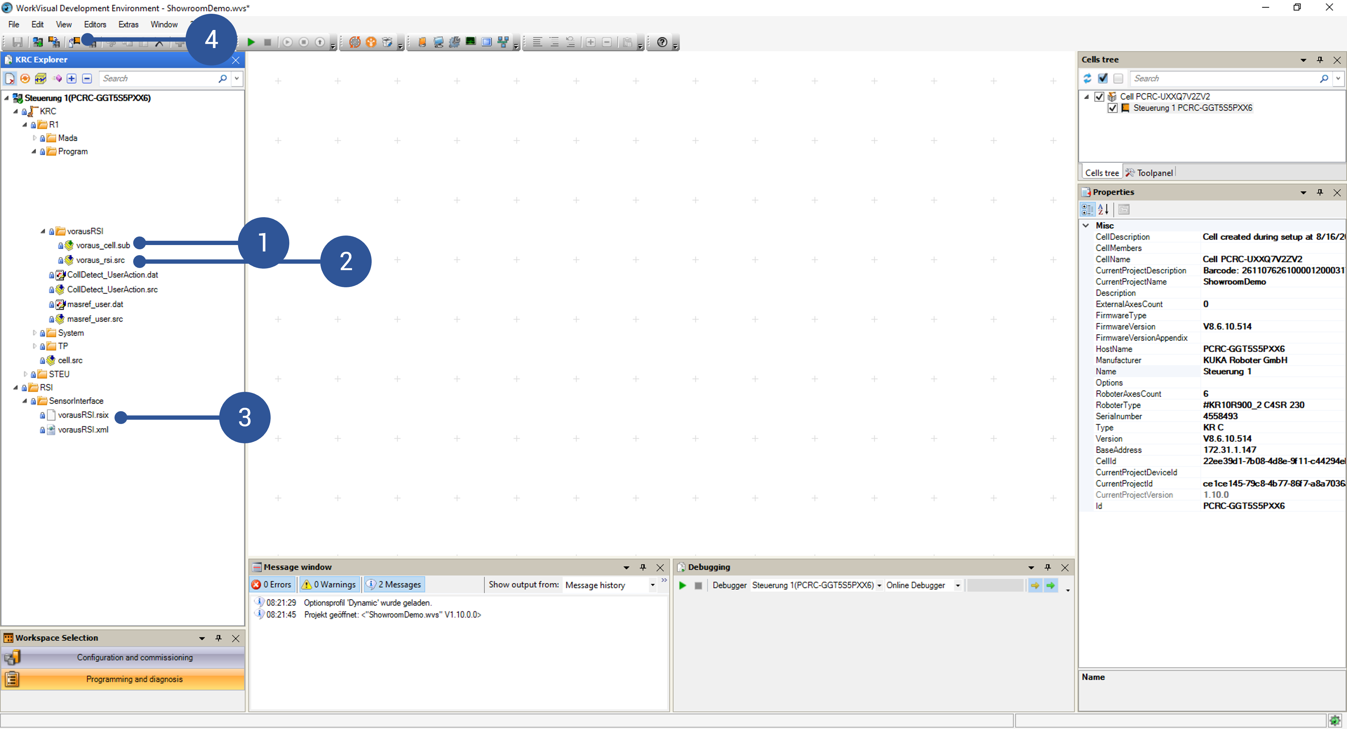
vorausRSI.rsixcontext file should be moved to “RSI/” -> “SensorInterface/” (Fig. 23/➌).Using WorkVisual, copy the
vorausRSI.xmlfile to the same directory as the RSI context file. If needed, modify the IP address of the voraus.ipc:<ROOT> <CONFIG> <IP_NUMBER>IP_of_the_voraus.ipc</IP_NUMBER> <PORT>59152</PORT> <SENTYPE>ImFree</SENTYPE> <ONLYSEND>FALSE</ONLYSEND> </CONFIG>Add the following line into the section
Userdefined VariablesofSystem/$config.datINT VORAUS_TOOL_ID = 16Copy the file
voraus_cell.subto the program directory of the robot, e.g., to “KRC” -> “R1/” -> “Program/” -> “vorausRSI/” (Fig. 23/➊).Copy the file
voraus_rsi.srcto the program directory of the robot, e.g., to “KRC” -> “R1/” -> “Program/” -> “vorausRSI/” (Fig. 23/➋).Afterwards, the files have to be uploaded to the robot. You have to be logged in at least as an “expert” on the KUKA smartPAD for this. Click Transfer changes to the controller as shown in Fig. 23/➍. Confirm the operation in the pop-up. When asked for remote access on the KUKA smartPAD, confirm it as well. When the pop-up disappears in WorkVisual, the process is complete.
On the smartPAD, configure the
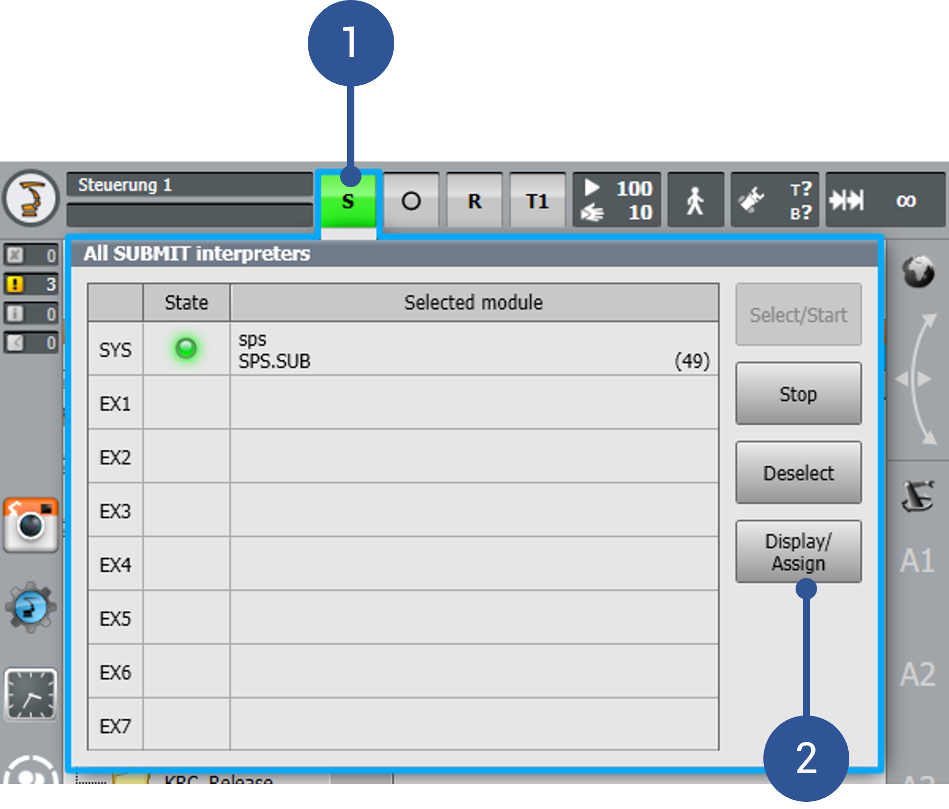
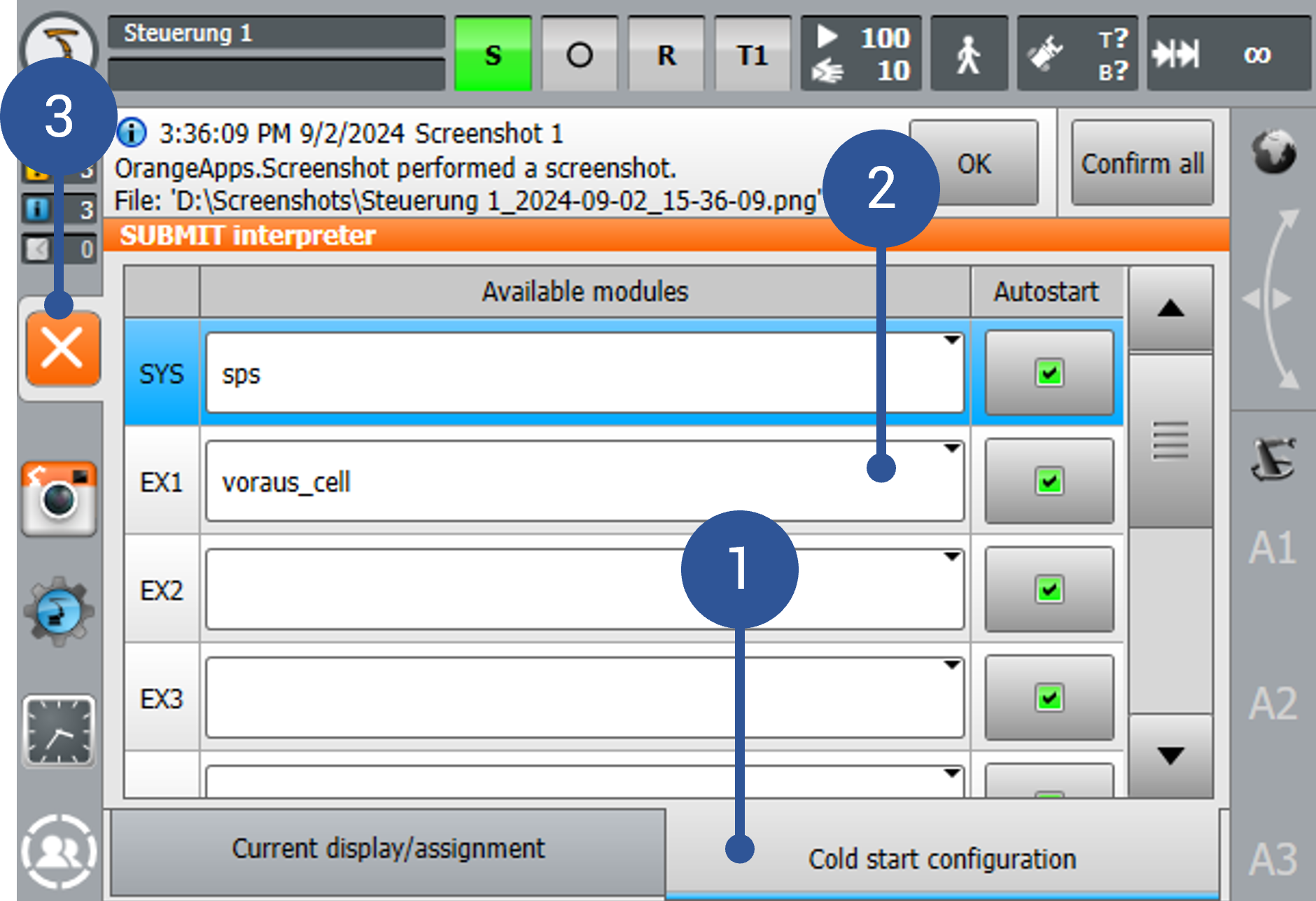
voraus_cell.subin the submit interpreter. This is only possible when logged in at least as an “expert”.Enter the Submit interpreter menu on the KUKA smartPAD (Fig. 24/➊).
Click Display/Assign (Fig. 24/➋).
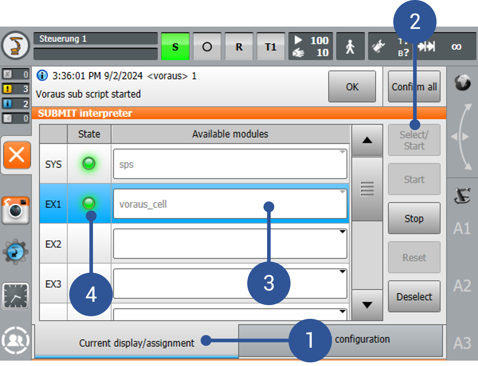
Enter Current Display/Assign (Fig. 25/➊)
Select the
voraus_cellscript in EX1 (Fig. 25/➌).Click Select/Start (Fig. 25/➋).
Check if
voraus_cellis running (Fig. 25/➍)
Enter the Cold start-configuration section (Fig. 26/➊) and select
voraus_cellat EX1 (Fig. 26/➋).Leave the screen (Fig. 26/➌)
After this procedure, the KUKA robot is ready to communicate with the voraus.core.
Configuration of Automatic External (AUT EXT)
This section describes the configuration of a KUKA robot for Automatic External (AUT EXT) operation.
The purpose of the Automatic External configuration is to allow the voraus.core to control the KUKA robot via digital I/O signals while the robot is in the EXT operating mode.
This enables the voraus.core to:
Establish the RSI connection by automatically starting the
voraus_rsi()script on the KRCSwitch the regulators on and off
Acknowledge faults
Note
The KUKA signals and the smartPAD refer to the regulators as drives. In this section, both terms describe the same state.
Configuration on the KUKA Controller
The following steps prepare the KRC for AUT EXT operation: deploying the required files, configuring the AUT EXT signals, and setting up the fieldbus connection to the voraus.ipc.
Required KRC Files
For the required voraus files, please refer to Robot Requirements, where all necessary files are listed.
The AUT EXT configuration builds on the RSI interface. Before continuing, make sure that all steps described in Setting up the RSI interface have been completed and that the files deployed there are up-to-date.
In addition, the file cell.src, which is listed in Robot Requirements as only needed for AUT EXT,
must be deployed to “KRC” -> “R1/” -> “cell.src”.
Also check that the following variable is added to the Userdefined Variables section in
“KRC” -> “R1/” -> “System/” -> “$config.dat”
BOOL VORAUS_RUN_RSI=TRUE
Automatic External Signal Configuration
The following Automatic External signals are used to communicate with the voraus.core. Each signal is assigned to a
KUKA digital input $IN[..] or output $OUT[..], which is then mapped to the fieldbus, see
Fieldbus Configuration. The fieldbus transfers the signals to the voraus.ipc, where the Automatic
External script processes them, see Automatic External Script on the voraus.ipc.
On the KUKA smartPAD:
Set the operating mode to T1.
Log in as Expert.
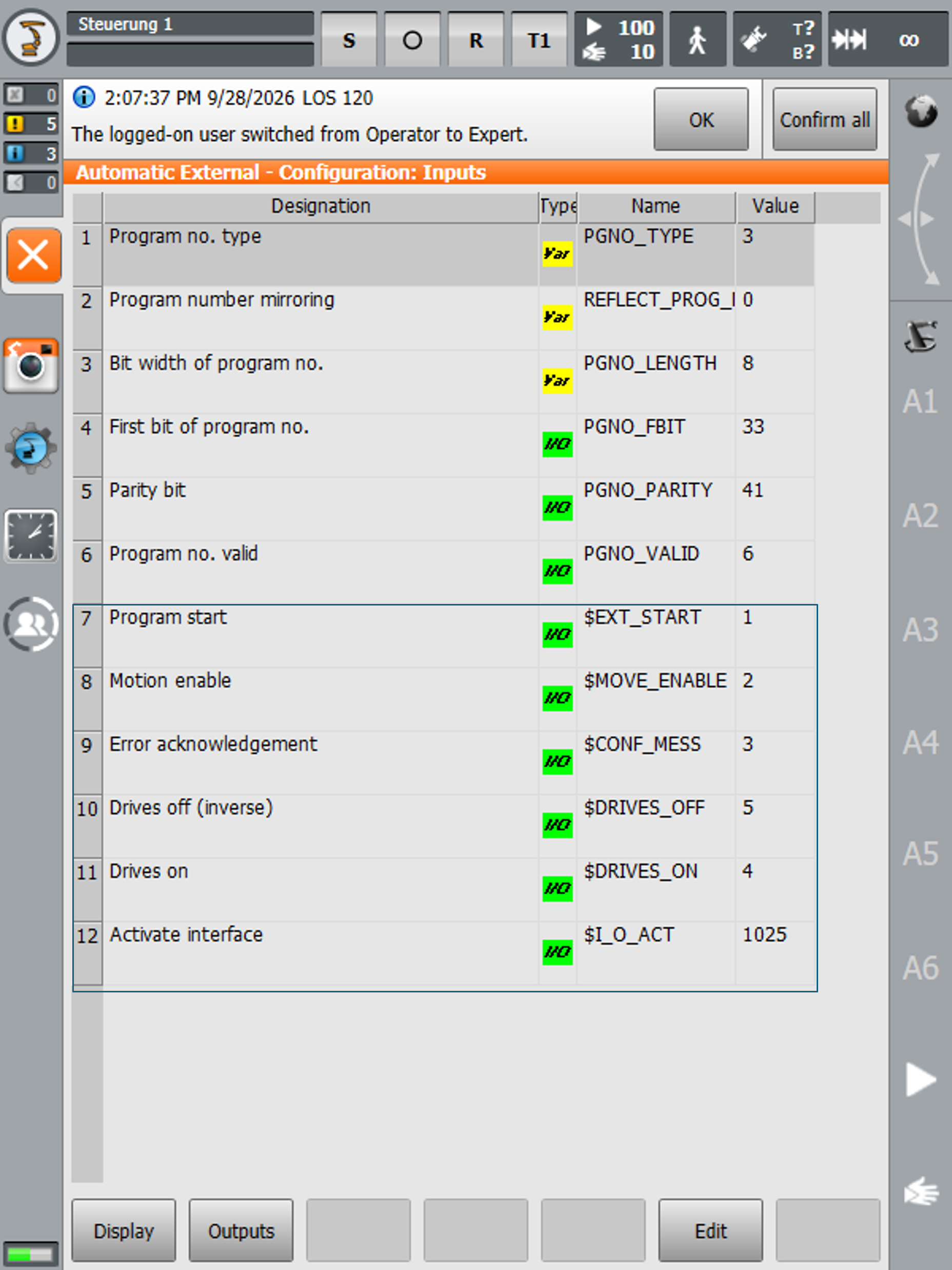
Open Main menu > Configuration > Inputs/outputs > Automatic External to view and configure the signal mapping (see Fig. 27).

In this example, the KUKA I/Os start at $IN[1] and $OUT[1]. Replace them with your own I/O list.
The inputs that the voraus.ipc sends to the KUKA controller are listed in Table 1.
Fig. 28 shows the corresponding input configuration on the smartPAD.
Note
Two KUKA inputs are fixed: $IN[1025] is always TRUE and $IN[1026] is always FALSE.
Note
The $MOVE_ENABLE input remains valid even in other operating modes.
For example, in T1, error KSS01376 “Active commands inhibited” may occur if the input is not set.
In this case, the input must be set to high or 1025 (always high).
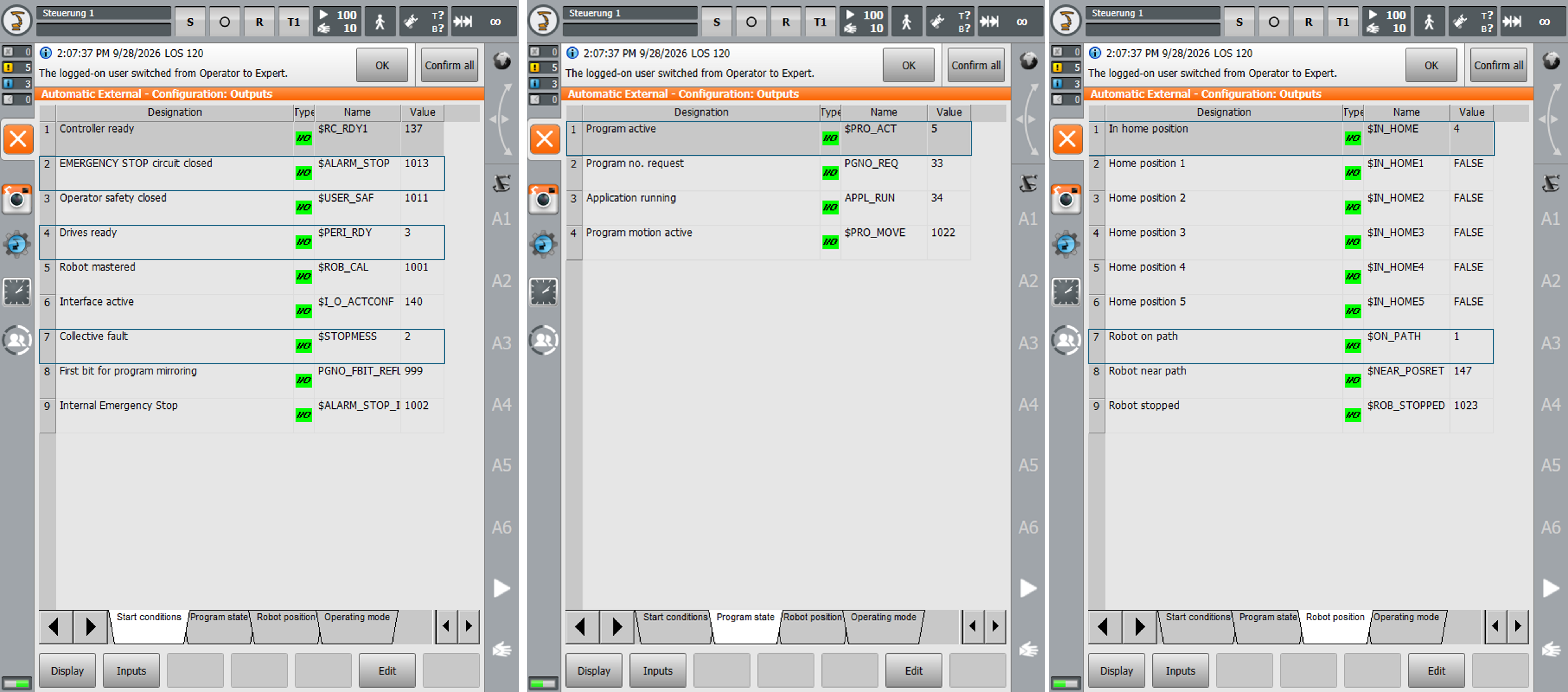
The outputs that the KUKA controller reports to the voraus.ipc are listed in Table 2. Fig. 29 shows the corresponding output configuration on the smartPAD.
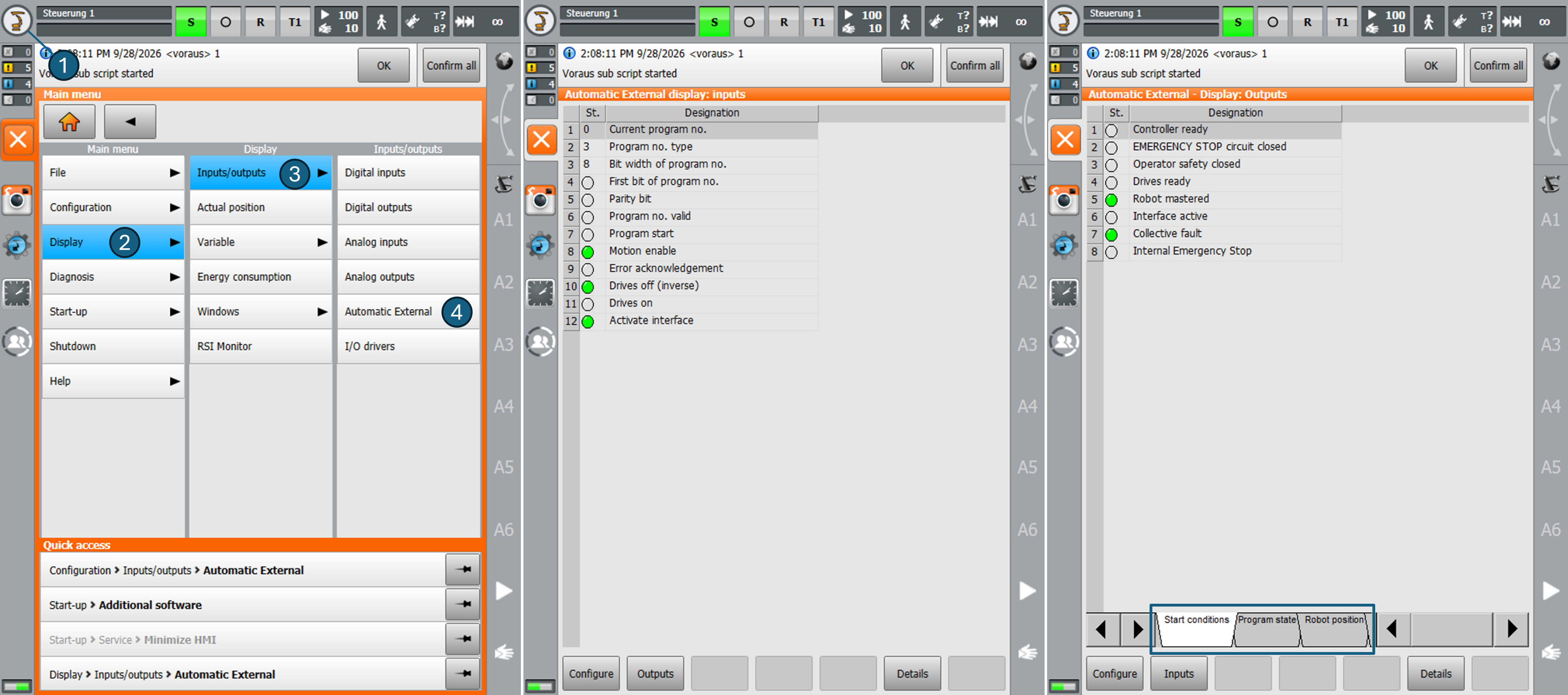
The current state of the Automatic External variables can be monitored on the smartPAD at Main menu (Fig. 30/➊) > Display (Fig. 30/➋) > Inputs/outputs (Fig. 30/➌) > Automatic External (Fig. 30/➍).
Configuration of Externally Acknowledgeable Messages
By default, KUKA restricts remote clearing of many system errors, forcing operators to switch to T1 mode to clear them manually.
The “Config:/” ->”User/” -> “Common/” -> “KRCExtConfMsg.xml” file is a configuration file used in KUKA Robot
Controllers (KRC2, KRC4, and KRC5) in which an allow-list is defined that enables external acknowledgment of specific
error messages via the $CONF_MESS digital input signal while the robot is operating mode EXT.
Note
Not all errors can be added to KRCExtConfMsg.xml. There are still errors that can only be reset manually on the smartPAD.
Adding Message Numbers in WorkVisual
Open the uploaded project and set the controller as active (right-click the controller > Set as active controller).
In the Project Structure window, select the Files tab (Fig. 31/➊).
Add your message number (Fig. 31/➌) to the configuration file “KRCExtConfMsg.xml” Fig. 31/➋.
We recommend adding the message number 1030 to the list:
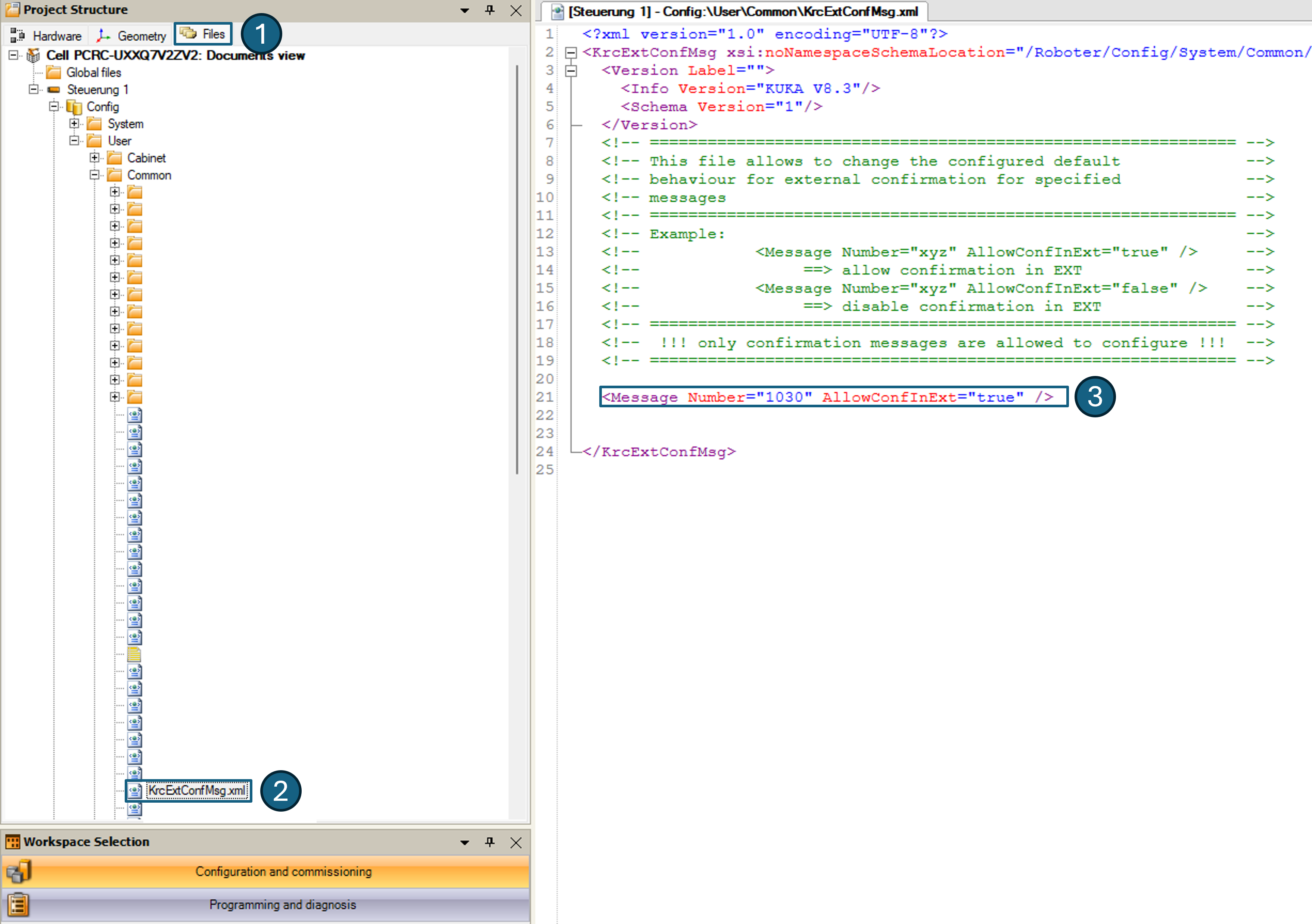
Fig. 31 Configuration of confirmable errors in Automatic External
Note
The message number displayed on the smartPAD always includes a leading zero (e.g., 01030). When entering the
number into the XML, the leading zero must be omitted, so the number becomes 1030. An entry such as
Number="01030" is silently rejected and not confirmable.
Fieldbus Configuration
Note
An example that uses PROFINET communication will be available soon.
The following example illustrates fieldbus communication between the voraus.ipc and the KUKA controller using a Beckhoff EtherCAT bridge (EL6695) and a Beckhoff EtherCAT coupler (EK1100), see Fig. 32.
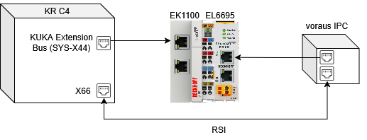
Fig. 32 Example of an EtherCAT communication between voraus.ipc and KUKA using Beckhoff I/O modules
Physical Installation
Power off: Turn off and lock out the robot controller (KR C4) completely before opening the cabinet.
Mount the modules: Snap the EtherCAT coupler (e.g., Beckhoff EK1100) and the EtherCAT bridge (e.g., Beckhoff EL6695) onto the DIN rail inside the controller cabinet.
Connect to the bus: Plug the bus cable from the coupler (EK1100) into the internal KUKA Extension Bus port (SYS-X44).
Connect to the voraus.ipc: Plug the bus cable from the bridge input (EL6695) into the voraus.ipc. The Ethernet port of the voraus.ipc will later be defined within the Docker Compose file of the voraus EtherCAT Master.
Power supply: Connect the external 24 V DC power supply to the power contacts of the EK1100 and the EL6695.
Note
This EtherCAT communication is completely separate from RSI communication. Do not make any changes to the RSI settings or cabling.
Fieldbus Configuration in WorkVisual
Start WorkVisual without selecting a project.
Import the device descriptions: File > Import/Export > Import device description file, select the Beckhoff ESI XML files (which can be downloaded from the Beckhoff website). Skip this step if the devices already appear in the DTM catalog.
Open your project via File > Open Project and set the controller as active (right-click the controller > Set as active controller).
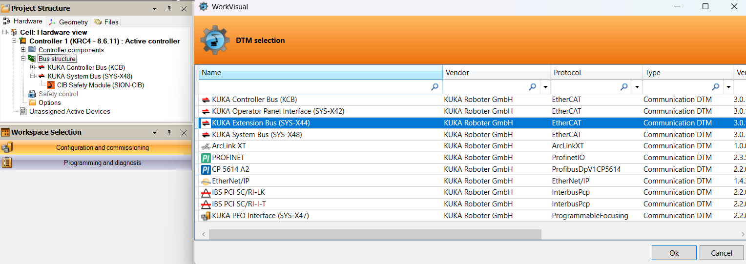
In the Hardware tab, expand the controller > Bus structure > KUKA Extension Bus (SYS-X44). If the extension bus is not present, right-click Bus structure > Add > select the KUKA Extension Bus (SYS-X44) (see Fig. 33).
Right-click KUKA Extension Bus (SYS-X44) > Add > select the EK1100 from the Beckhoff catalog (see Fig. 34).
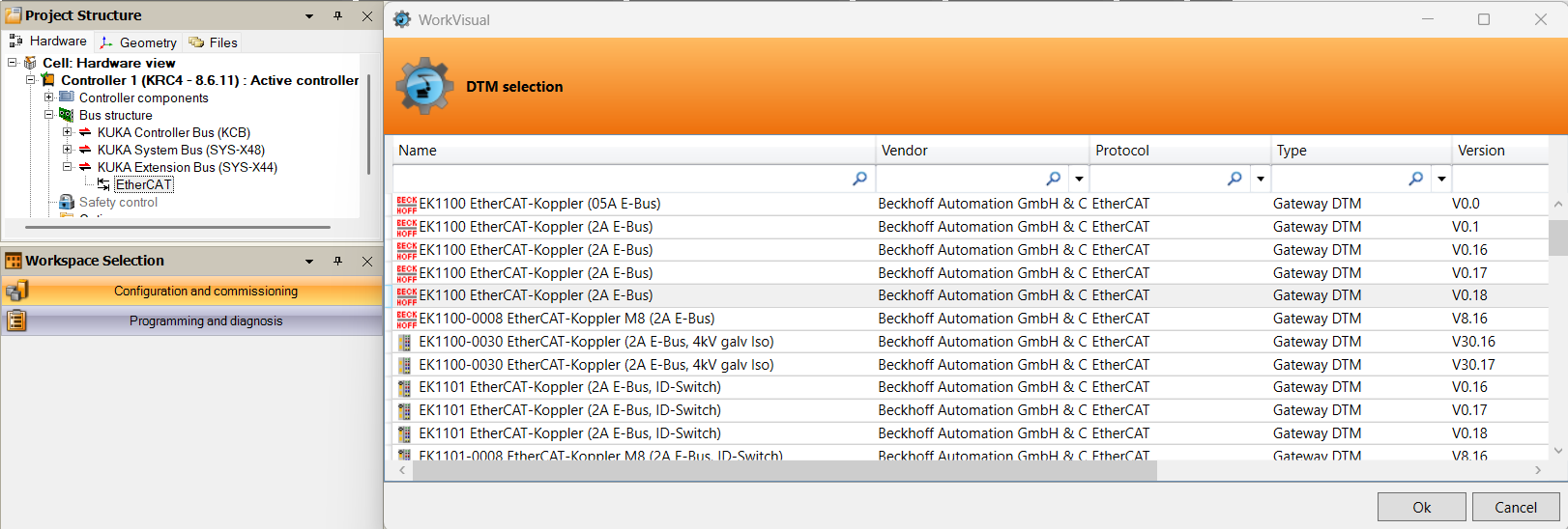
Right-click EK1100 > Add > select the EL6695 from the Beckhoff catalog (see Fig. 35).

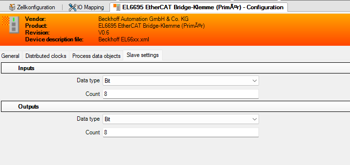
Double-click on the EL6695 in the device tree and navigate to the tab Slave settings. Then configure 8 bit for the Inputs and Outputs respectively, as seen in Fig. 36.
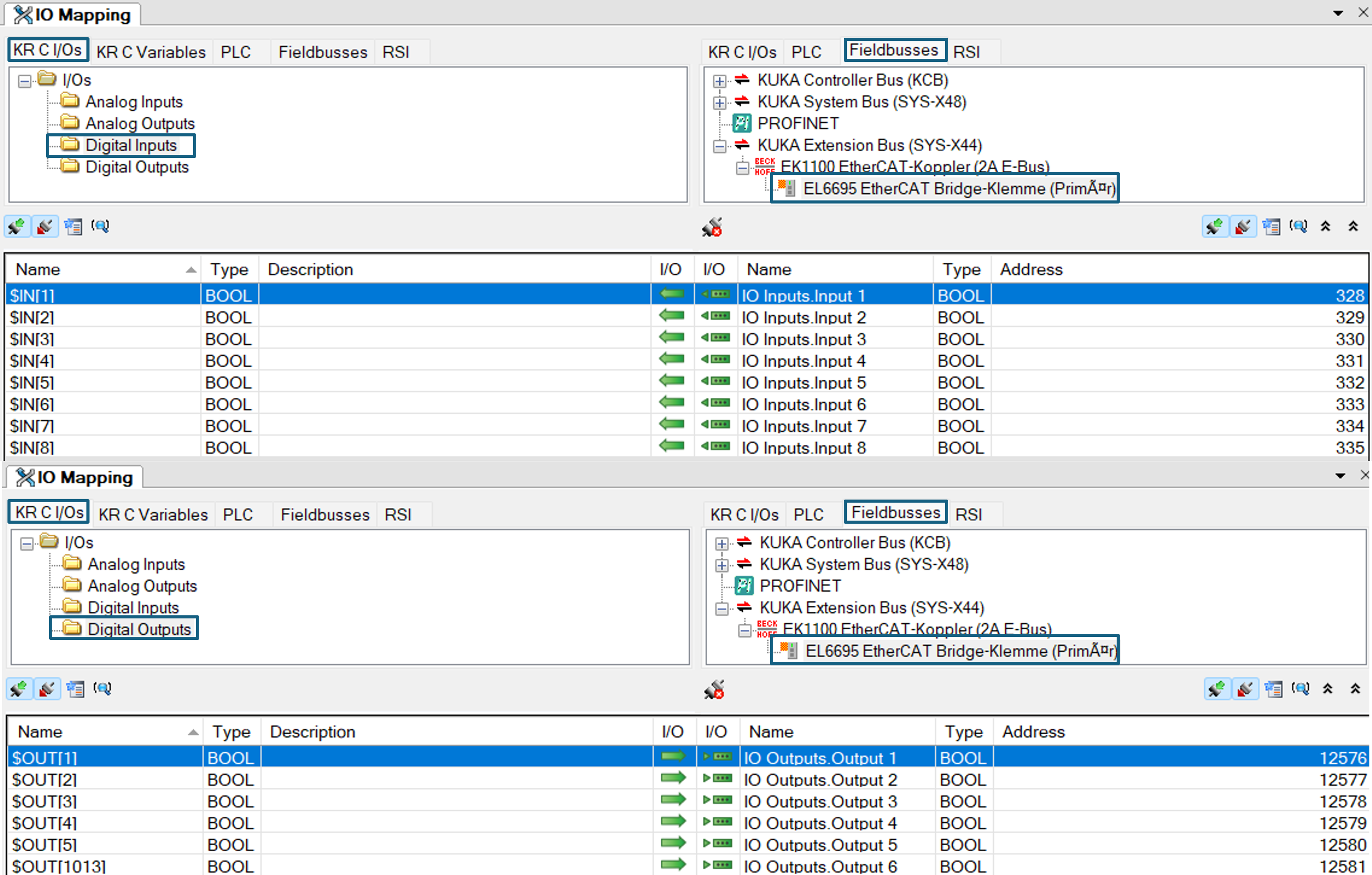
Open the I/O Mapping window (Editors > I/O Mapping). In the left pane, select KR C I/Os > Digital inputs or Digital outputs. In the right pane, select Fieldbuses and the EL6695 channels.
Connect the KUKA inputs to the EL6695 channels by selecting the KUKA I/O on the left and the EL6695 I/O on the right, then right-click > Connect. Repeat for all configured Automatic External inputs and outputs listed in Table 1 and Table 2. The result is shown in Fig. 37.
Click Extras > Generate code, then File > Deploy (or Install) and confirm the activation on the smartPAD (user group Expert, operating mode T1).
Configuration on the voraus.ipc
On the voraus.ipc, an Automatic External script processes the signals received via the fieldbus and connects them to the voraus.core.
Configuration of the voraus EtherCAT Master on the voraus.ipc
The voraus EtherCAT Master handles the communication between the voraus.ipc and the EtherCAT I/O modules. It runs in a separate Docker container alongside the voraus.core.
To configure the voraus EtherCAT Master, follow the instructions in the voraus EtherCAT Master documentation.
Key steps are:
Create an ENI file for the EtherCAT I/O modules. It can be generated by an EtherCAT engineering tool such as Beckhoff TwinCAT.
Add the voraus EtherCAT Master to the Docker Compose file and mount the ENI file to the container.
Generate the Python code.
An example implementation of the voraus EtherCAT Master in the Docker Compose file is shown in Listing 1.
ethercat-master:
  image: voraus.jfrog.io/docker/voraus-ethercat-master:2.2.0
  network_mode: host  # needed for raw socket communication
  pid: host           # needed for CodeMeter runtime on host
  cap_add:
    - CAP_NET_ADMIN # needed for setting the interface into promiscuous mode
    - CAP_NET_RAW   # needed for raw socket communication
    - CAP_IPC_LOCK  # needed for memory locking
    - CAP_SYS_NICE  # needed for using SCHED_FIFO with a priority
  devices:
    - /dev/cpu_dma_latency:/dev/cpu_dma_latency # needed for sleep state prevention
  volumes:
    - ./data/:/root/data/ # contains ENI file and logs
  environment:
    - ECAT_ENI=/root/data/eni.xml  #<-- replace with your ENI file path
    - ECAT_CYCLETIME=2000
    - ECAT_INTERFACE=${INTERFACE} #<-- connection to EL6695
    - ECAT_LOG_DIR=/root/data/log
    - ECAT_OPCUA_PORT=${OPCUA_PORT} #<-- e.g., 48409
    - ECAT_CPU_AFFINITY=2
    - ECAT_PRIORITY=49
  restart: on-failure
Automatic External Script on the voraus.ipc
Finally, a Python script needs to run on the voraus.ipc to read and write the I/O signals and to step through the Automatic External sequence. To request an example script, contact voraus support.
Add the Python script to the Docker Compose file so that it starts automatically with the other containers. The Python script has the following tasks:
It steps through the Automatic External process, e.g., it acknowledges errors and switches the regulators on and off (
$CONF_MESS,$DRIVES_ON,$DRIVES_OFF, see Table 1).It reads and writes the I/O signals from and to the KUKA controller via the fieldbus.
It communicates with the voraus.core and sets an error if
$ALARM_STOPis triggered, see Table 2.It reacts to the commands from the voraus.core for switching the regulators on and off and for resetting errors.
An example service definition for the Automatic External script (EtherCAT) in the Docker Compose file is shown in Listing 2 and the needed Dockerfile is shown in Listing 3.
autext:
  depends_on:
    ethercat-master:
      condition: service_healthy
  build:
    context: .
    args:
      PIP_INDEX_URL: https://artifactory.vorausrobotik.com/artifactory/api/pypi/pypi/simple
  network_mode: host
  restart: on-failure
  volumes:
    - .:/app
  command: ["python", "autExtEtherCatTask.py"]
Show Dockerfile
 1FROM python:3.12-slim
 2
 3WORKDIR /app
 4
 5# Requires build-time network access to wibu-packages.vorausrobotik.com (VPN/company network).
 6RUN apt-get update && apt-get install -y --no-install-recommends \
 7        gnupg2 curl libusb-1.0-0 \
 8    && curl -sf --compressed https://wibu-packages.vorausrobotik.com/ubuntu/wibu-packages-maintainers.gpg \
 9        | gpg --dearmor -o /usr/share/keyrings/wibu-package-maintainers.gpg \
10    && echo "deb [arch=amd64 signed-by=/usr/share/keyrings/wibu-package-maintainers.gpg] https://wibu-packages.vorausrobotik.com/ubuntu/ ./" \
11        > /etc/apt/sources.list.d/voraus-wibu.list \
12    && apt-get update \
13    && apt-get install -y --no-install-recommends codemeter-lite axprotector \
14    && rm -rf /var/lib/apt/lists/*
15
16RUN sed -i 's/^IsNetworkServer=.*/IsNetworkServer=0/' /etc/wibu/CodeMeter/Server.ini \
17    && printf '\n[ServerSearchList\\Server2]\nAddress=licenses.vorausrobotik.com\n' \
18        >> /etc/wibu/CodeMeter/Server.ini
19
20# Requires build-time network access to artifactory.vorausrobotik.com.
21ARG PIP_INDEX_URL=https://artifactory.vorausrobotik.com/artifactory/api/pypi/pypi/simple
22ENV PIP_INDEX_URL=${PIP_INDEX_URL} \
23    PYTHONUNBUFFERED=1
24
25COPY requirements.txt .
26RUN pip install --no-cache-dir -r requirements.txt
27
28COPY entrypoint.sh /entrypoint.sh
29RUN chmod +x /entrypoint.sh
30
31ENTRYPOINT ["/entrypoint.sh"]
Testing the Automatic External Behavior
Check the Automatic External behavior as follows:
Start the voraus Docker stack and the KUKA controller.
Switch the KUKA controller to the operating mode EXT (Fig. 38/➊).
/R1/CELLis selected automatically (Fig. 38/➋).The regulators are off (Fig. 38/➌), and
RSI_MOVECORRis not active.On the voraus side, the robot is in the
STANDBYstate.

Fig. 38 Initial state after switching to EXT on the KUKA smartPAD
Switch the regulators on from the voraus side, either in the voraus.operator or by starting a voraus Robot Arm script:
The regulators turn on (Fig. 39/➊).
/R1/voraus_rsiis running (Fig. 39/➋) in stepRSI_MOVECORR(Fig. 39/➌).On the voraus side, the robot is in the
READYstate, and its pose is updated in the voraus 3D Visu.

Switch the regulators off from the voraus side, either in the voraus.operator or by waiting until a voraus Robot Arm script has been completed without errors:
The regulators turn off (Fig. 40/➊).
/R1/voraus_rsiis still selected (Fig. 40/➋), but stopped (indicated by a red R, Fig. 40/➌).RSI_MOVECORRis no longer active (Fig. 40/➍).On the voraus side, the robot is in the standby state.

The regulators can be turned on again, as described in step 3.
Trigger an error, for example, by pressing and releasing the emergency stop button without acknowledging it:
The regulators turn off (Fig. 41/➊).
/R1/voraus_rsiis still selected (Fig. 41/➋), but stopped (indicated by a red R, Fig. 41/➌).RSI_MOVECORRis no longer active (Fig. 41/➍).On the voraus side, the robot is in the ERROR state.

Send a reset request via the voraus.operator or
voraus-error-handler.The system tries to reset all errors on the voraus and KUKA side. KUKA messages that cannot be acknowledged externally by default can be added to the
KRCExtConfMsg.xmlfile, see Configuration of Externally Acknowledgeable Messages.After a successful reset, the regulators can be turned on again. The robot is in the same state as described in step 2.
/R1/CELLis selected (Fig. 42/➊).The regulators are off (Fig. 42/➋), and
RSI_MOVECORRis not active (Fig. 42/➌).On the voraus side, the robot is in the standby state.

Fig. 42 KUKA Automatic External after a successful error reset
Next Steps
The installation of the voraus.core is now complete. Continue with the configuration of the software stack for your setup as described in Configuration for the voraus.core.
After the configuration, the voraus.core can be started and activated as described in Starting, Stopping, and Activating the voraus.core.